Scc/escc user manual – Zilog Z80230 User Manual
Page 117
SCC/ESCC
User Manual
UM010903-0515
Data Communication Modes
110
A summary is listed in
on page 111. Refer to a detailed example of using the SCC in 16-bit
sync mode is available in the application note SCC in Binary Synchronous Communications.
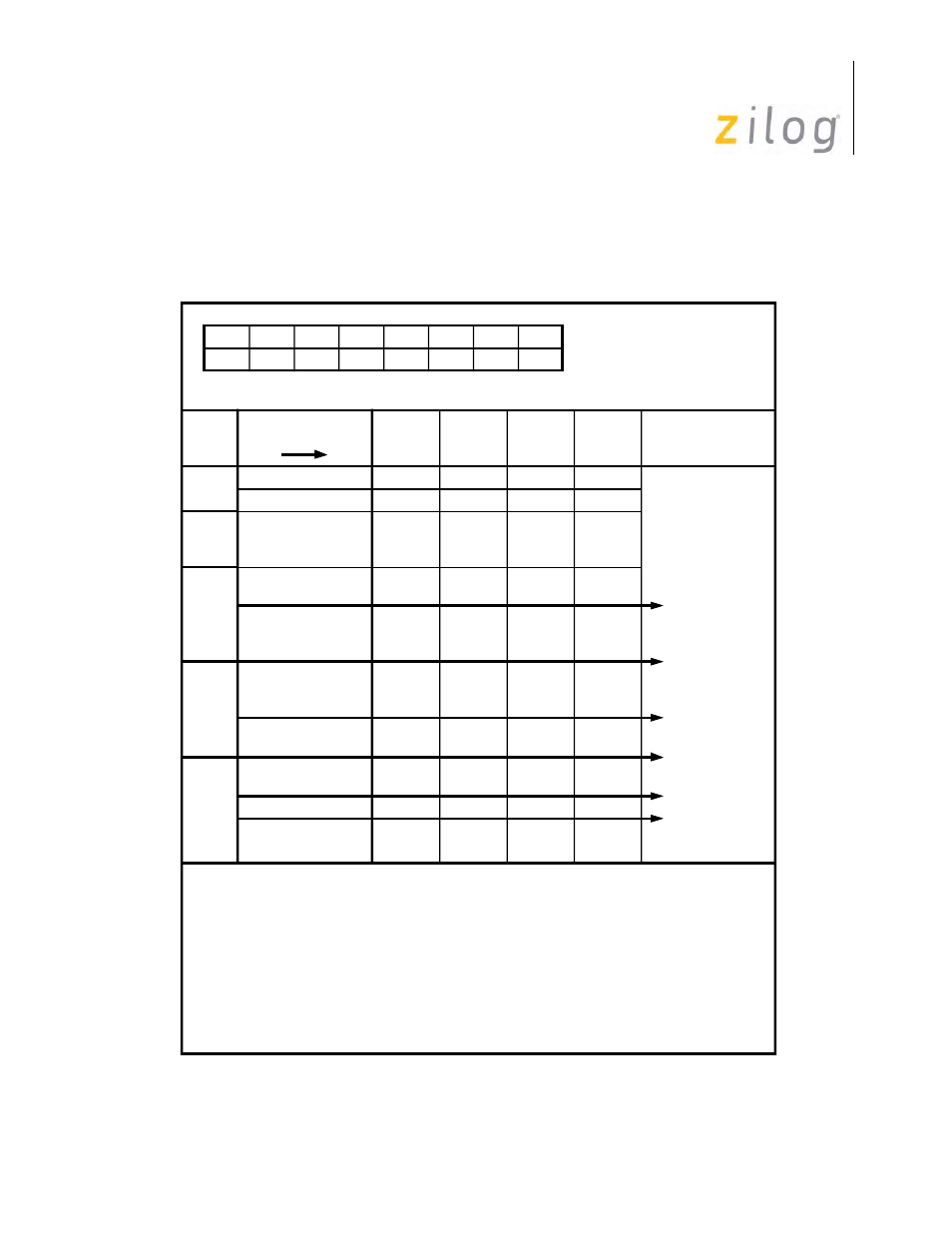
Enabling and Disabling CRC
Direction of Data
Coming into SCC
Shift
Register
Delay
Register
CRC
Notes
H G F E D C B
H G F E D C
H G F E D
CPU Read
CPU Enables CR
H G F E
CPU Read
H G F E
CPU Read
CPU Disables CR
H G F
CPU Read
CPU Enables CR
H G
CPU Read
H
CPU Reads & Disca
Read RR1 D
Read H & Disca
A
d
d
B
B
d
C
D
E
F
G
H
C
D*
E
F
G
B
C
D
E
F
e
e
d
e
e
H
G
e
H
CRC Calc on B
CRC Calc on C
CRC Calc is
Disabled on D
CRC Calc on E
CRC Calc on F
CRC Calc on F
Result latched in
Error FIFO †
* Usually D is a end-of-message character indicator.
† The status is latched on the Error FIFO for each received byte. In the calculation of F,
the CRC error flag in the Error FIFO will be 0 for an error free message.
d = disabled
e = enabled
A B C D E F G H
A = SYNC
B - F = Data with E = CRC1 and F = CRC2
G and H are arbitrary data (Pad Character)
Legend:
A
Note: No CRC Calculation on "D"
(Sync)
B
(Data1)
C
(Data2)
D
(Data3)
E
(CRC1)
F
(CRC2)
G
(Data)
H
(Data)
Stage
1
2
3
4
5
Receive
Data FIFO