Bit-oriented synchronous (sdlc/hdlc) mode – Zilog Z80230 User Manual
Page 120
SCC/ESCC
User Manual
UM010903-0515
Data Communication Modes
113
Bit-oriented Synchronous (SDLC/HDLC) Mode
Synchronous Data Link Control mode (SDLC) uses synchronization characters similar to Bisync
and Monosync modes (such as flags and pad characters). It is a bit-oriented protocol instead of a
byte-oriented protocol. High level Data Link Control (HDLC) is defined as CCITT, also EIAJ and
other standards; SDLC is one of the implementations made by IBM. The SDLC protocol uses the
technique of zero insertion to make all data transparent from SYNC characters. All references to
SDLC in this manual apply to both SDLC and HDLC.
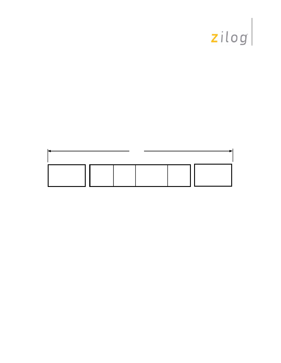
The basic format for SDLC is a frame (
). A Frame is marked at the beginning and end by a
unique flag pattern. The flags enclose an address, control, information, and frame check fields.
There are many different implementations of the SDLC protocol and many do not use all of the
fields. The SCC provides many features to control how each of the fields is received and transmit-
ted.
SDLC Message Format
Frames of information are enclosed by a unique bit pattern called a flag. The flag character has a
bit pattern of “01111110” (7E Hex). This sequence of six consecutive ones is unique because all
data between the opening and closing flags is prohibited from having more than five consecutive
1s. The transmitter guarantees this by watching the transmit data stream and inserting a 0 after five
consecutive 1s, regardless of character boundaries. In turn, the receiver searches the receive data
stream for five consecutive 1s and deletes the next bit if it is a 0. Since the SDLC mode does not
use characters of defined length, but rather works on a bit-by-bit basis, the 01111110 flag can be
recognized at any time. Inserted and removed 0s are not included in the CRC calculation. Since
the transmission of the flag character is excluded from the zero insertion logic, its transmission is
guaranteed to be seen as a flag by the receiver. The zero insertion and deletion is completely trans-
parent to the user.
Because of the zero insertion/deletion, actual bit length on the transmission line may be longer
than the number of bits sent.
The two flags that delineate the SDLC frame serve as reference points when positioning the
address and control fields, and they initiate the transmission error check. The ending flag indicates
to the receiving station that the 16 bits just received constitute the frame check (CRC; also referred
to as FCS or Frame Check Sequence). The ending flag can be followed by another frame, another
Beginning Flag
01111110
8 Bits
Frame
Check
16 Bits
Information
Any Number
Of Bits
Address
8 Bits
Control
8 Bits
Ending Flag
01111110
8 Bits
Frame