Write register 3 (receive parameters and control) – Zilog Z80230 User Manual
Page 155
SCC/ESCC
User Manual
UM010903-0515
Register Descriptions
148
Write Register 3 (Receive Parameters and Control)
This register contains the control bits and parameters for the receiver logic as displayed in
On the ESCC and 85C30, with the Extended Read option enabled, this register may be read as
RR9.
Write Register 3
Bits 7 and 6: Receiver Bits/Character
The state of these two bits determines the number of bits to be assembled as a character in the
received serial data stream. The number of bits per character can be changed while a character is
being assembled, but only before the number of bits currently programmed is reached. Unused bits
in the Received Data Register (RR8) are set to 1 in asynchronous modes. In Synchronous and
SDLC modes, the SCC merely transfers an 8-bit section of the serial data stream to the Receive
FIFO at the appropriate time.
lists the number of bits per character in the assembled charac-
ter format.
Receive Bits per Character
D7
D6
Bits/Character
0
0
5
0
1
7
1
0
6
1
1
8
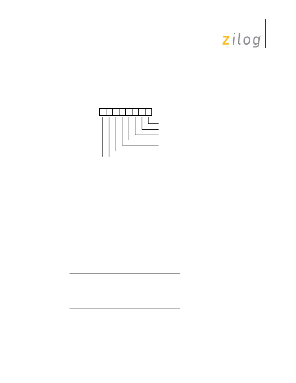
D7 D6 D5 D4 D3 D2 D1 D0
Write Register 3
Rx Enable
0 0 Rx 5 Bits/Character
0 1 Rx 7 Bits/Character
1 0 Rx 6 Bits/Character
1 1 Rx 8 Bits/Character
Sync Character Load Inhibit
Address Search Mode (SDLC)
Rx CRC Enable
Enter Hunt Mode
Auto Enables