Sdlc loop mode, Figure – Zilog Z80230 User Manual
Page 137
SCC/ESCC
User Manual
UM010903-0515
Data Communication Modes
130
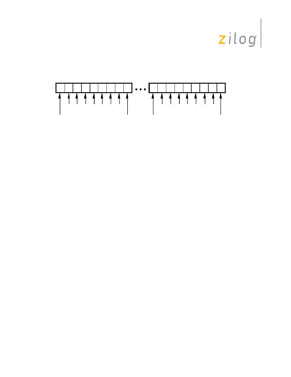
SDLC Byte Counting Detail
SDLC Status FIFO Anti-Lock Feature (ESCC only).
When the Frame Status FIFO is enabled
and the ESCC is programmed for Special Receive Condition Only (WR1 D4=D3=1), the data
FIFO is not locked when a character with End of Frame status is read. When a character with the
EOF status reaches the top of the FIFO, an interrupt with a vector for receive data is generated.
The command Reset Highest IUS must be issued at the end of the interrupt service routine regard-
less of whether an interrupt acknowledge cycle had been executed (hardware or software). This
allows a DMA to complete a transfer of the received frame to memory and then interrupt the CPU
that a frame has been completed without locking the FIFO. Since in the Receive Interrupt on Spe-
cial Condition Only mode the interrupt vector for receive data is not used, it is used to indicate that
the last byte of a frame has been read from the Receive FIFO. This eliminates having to read the
frame status (CRC and other status is stored in the status FIFO with the frame byte count).
When a character with a special receive condition other than EOF is received (receive overrun, or
parity), a special receive condition interrupt is generated after the character is read from the FIFO
and the Receive FIFO is locked until the Error Reset command is issued.
SDLC Loop Mode
The SCC supports SDLC Loop mode in addition to normal SDLC. SDLC Loop mode is very sim-
ilar to normal SDLC but is usually used in applications where a point-to-point network is not
appropriate (for example, Point-of-Sale terminals). In an SDLC Loop, there is a primary controller
that manages the message traffic flow on the loop and any number of secondary stations. In SDLC
Loop mode, the SCC operating in regular SDLC mode can act as the primary controller.
A secondary station in an SDLC Loop is always listening to the messages being sent around the
loop, and in fact must pass these messages to the rest of the loop by retransmitting them with a
one-bit-time delay.
00
00
00
00
F A D D D D C C F
F A D D D D C C F
0
4
1 2 3
5 6 7 0
0
4
1 2
3
5 6 7
Internal Byte Strobe
Increments Counter
Internal Byte Strobe
Increments Counter
Don't Load
Counter On
1st Flag
Reset Byte
Counter Here
Reset
Byte Counter
Load Counter
Into FIFO and
Increment PTR
Reset
Byte Counter
Reset
Byte Counter
Load Counter
Into FIFO And
Increment PTR