Dpll digital phase-locked loop – Zilog Z80230 User Manual
Page 85
SCC/ESCC
User Manual
UM010903-0515
SCC/ESCC Ancillary Support Circuitry
78
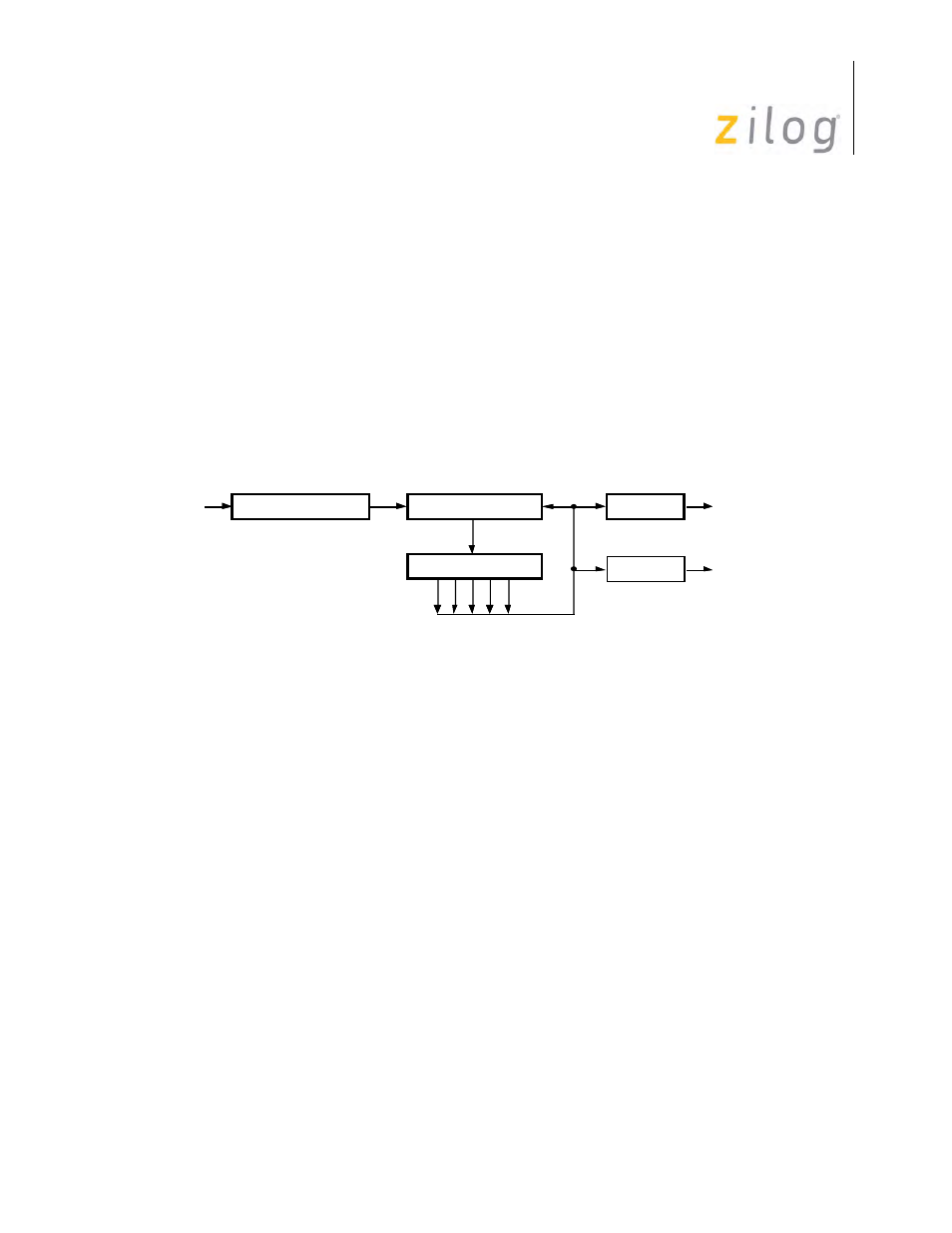
DPLL Digital Phase-Locked Loop
Each channel of the SCC contains a digital phase-locked loop that can be used to recover clock
information from a data stream with NRZI, FM, NRZ, or Manchester encoding. The DPLL is
driven by a clock nominally at 32 (NRZI) or 16 (FM) times the data rate. The DPLL uses this
clock, along with the data stream, to construct a receive clock for the data. This clock can then be
used as the SCC receive clock, the transmit clock, or both.
displays a block diagram of the digital phase-locked loop. It consists of a 5-bit counter, an
edge detector, and a pair of output decoders. The clock for the DPLL comes from the output of a
two-input multiplexer, and the two outputs go to the transmitter and receive clock multiplexers.
The DPLL is controlled by seven commands encoded in WR14 bits D7, D6 and D5.
Digital Phase-Locked Loop
The clock source for the DPLL is selected issuing one of the two commands in WR14, that is:
WR14 (7-5) = 100 selects the BRG
WR14 (7-5) = 101 selects the /RTxC pin
The first command selects the baud rate generator as the clock source. The other command selects
the /RTxC pin as the clock source, independent of whether the /RTxC pin is a simple input or part
of the crystal oscillator circuit.
Initialization of the DPLL is done at any time during the initialization sequence, but should be
done after the clock modes have been selected in WR11, and before the receiver and transmitter
are enabled. When initializing the DPLL, the clock source should be selected first, followed by the
selection of the operating mode.
To avoid metastable problems in the counter, the clock source selection is made only while DPLL
is disabled, since arbitrarily narrow pulses are generated at the output of the multiplexer when it
changes status.
The DPLL is programmed to operate in one of two modes, as selected by commands in WR14.
WR14 (7-5) = 111 selects NRZI mode
Edge Detector
RxD
Count Modifier
Decode
Receive
Clock
5-Bit Counter
Decode
Transmit
Clock