Crystal oscillator, Br g, Dp l l – Zilog Z80230 User Manual
Page 94
SCC/ESCC
User Manual
UM010903-0515
SCC/ESCC Ancillary Support Circuitry
87
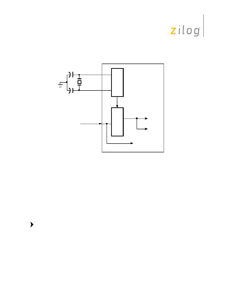
Synchronous Transmission, 1x Clock Rate, FM Data Encoding, using DPLL
Crystal Oscillator
Each channel contains a high gain oscillator amplifier for use with an external crystal circuit. The
amplifier is available between the /RTxC pin (crystal input) and the /SYNC pin (crystal output) for
each channel.
The oscillator amplifier is enabled by writing WR11 D7=1. While the crystal oscillator is enabled,
anything that has selected the /RTxC pin as its clock source automatically connects to the output of
the crystal oscillator.
The output of the oscillator amplifier can be programmed to output on the /TRxC pin,
which is particularly valuable for diagnostic purposes. Because amplifier characteristics
can be affected by the impedance of measurement equipment applied directly to the crystal
circuit, using the /TRxC pin allows the oscillation to be tested without affecting the circuit.
Of course, since the oscillator uses the /RTxC and /SYNC pins, this precludes the use of these pins
for other functions. In synchronous modes, no sync pulse is output, and the External Sync mode
cannot be selected. In asynchronous modes, the state of the Sync/
RxC
B
R
G
16x Data Rate
/RTxC Pin
/SYNC Pin
D
P
L
L
TxC
RxD Pin
RxD
External
Crystal
Note: