Write register 2 (interrupt vector) – Zilog Z80230 User Manual
Page 154
SCC/ESCC
User Manual
UM010903-0515
Register Descriptions
147
Bit 1: Transmitter Interrupt Enable
If this bit is set to 1, the transmitter requests an interrupt whenever the transmit buffer becomes
empty.
Bit 0: External/Status Master Interrupt Enable
This bit is the master enable for External/Status interrupts including /DCD, /CTS, /SYNC pins,
break, abort, the beginning of CRC transmission when the Transmit/Underrun/EOM latch is set, or
when the counter in the baud rate generator reaches 0. Write Register 15 contains the individual
enable bits for each of these sources of External/Status interrupts. This bit is reset by a channel or
hardware reset.
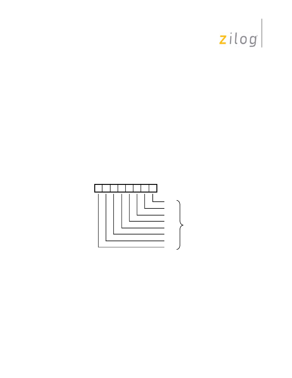
Write Register 2 (Interrupt Vector)
WR2 is the interrupt vector register. Only one vector register exists in the SCC, and it can be
accessed through either channel. The interrupt vector can be modified by status information. This
is controlled by the Vector Includes Status (VIS) and the Status High/Status Low bits in WR9. The
bit positions for WR2 are displayed in
Write Register 2
D7 D6 D5 D4 D3 D2 D1 D0
Write Register 2
V0
V1
V2
V3
V4
V5
V6
V7
Interrupt
Vector