Table – Zilog Z80230 User Manual
Page 130
SCC/ESCC
User Manual
UM010903-0515
Data Communication Modes
123
Residue Codes
As indicated in the table, these bits allow the processor to determine those bits in the information
(and not CRC) field. This allows transparent retransmission of the received frame. The Residue
Code bits do not go through a FIFO, so they change in RR1 when the last character of the frame is
loaded into the receive data FIFO. If there are any characters already in the receive data FIFO the
Residue Code is updated before they are read by the processor.
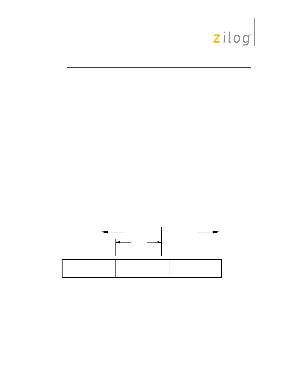
As an example of how the codes are interpreted, consider the case of eight bits per character and a
residue code of 101. The number of valid bits for the previous, second previous, and third previous
bytes are 0, 7, and 8, respectively. This indicates that the information field (Ifield) boundary falls
on the second previous byte as displayed in
.
Residue Code 101 Interpretation
A frame is terminated by the detection of a closing flag. Upon detection of the flag the following
actions take place: the contents of the Receive Shift Register are transferred to the receive data
FIFO; the Residue Code is latched, the CRC Error bit is latched; the End of Frame upon reaching
Residue
Code
Bits in Previous Byte
Bits in Second Previous
Byte
Bits in Third Previous
Byte
2 1 0 8B/C 7B/C 6B/C 5B/C 8B/C 7B/C 6B/C 5B/C 8B/C 7B/C 6B/C 5B/C
1 0 0 0
0
0
0
3
1
0
0
8
7
5
2
0 1 0 0
0
0
0
4
2
0
0
8
7
6
3
1 1 0 0
0
0
0
5
3
1
0
8
7
6
4
0 0 1 0
0
0
0
6
4
2
0
8
7
6
5
1 0 1 0
0
0
0
7
5
3
1
8
7
6
5
0 1 1 0
0
0
8
6
4
8
7
6
1 1 1 1
0
8
7
8
7
0 0 0 2
8
8
Third Previous
Byte
7-Bits
Second Previous
Byte
Previous
Byte
I - Field
CRC Field