Zilog Z80230 User Manual
Page 273
SCC/ESCC
User Manual
UM010903-0515
Application Notes
266
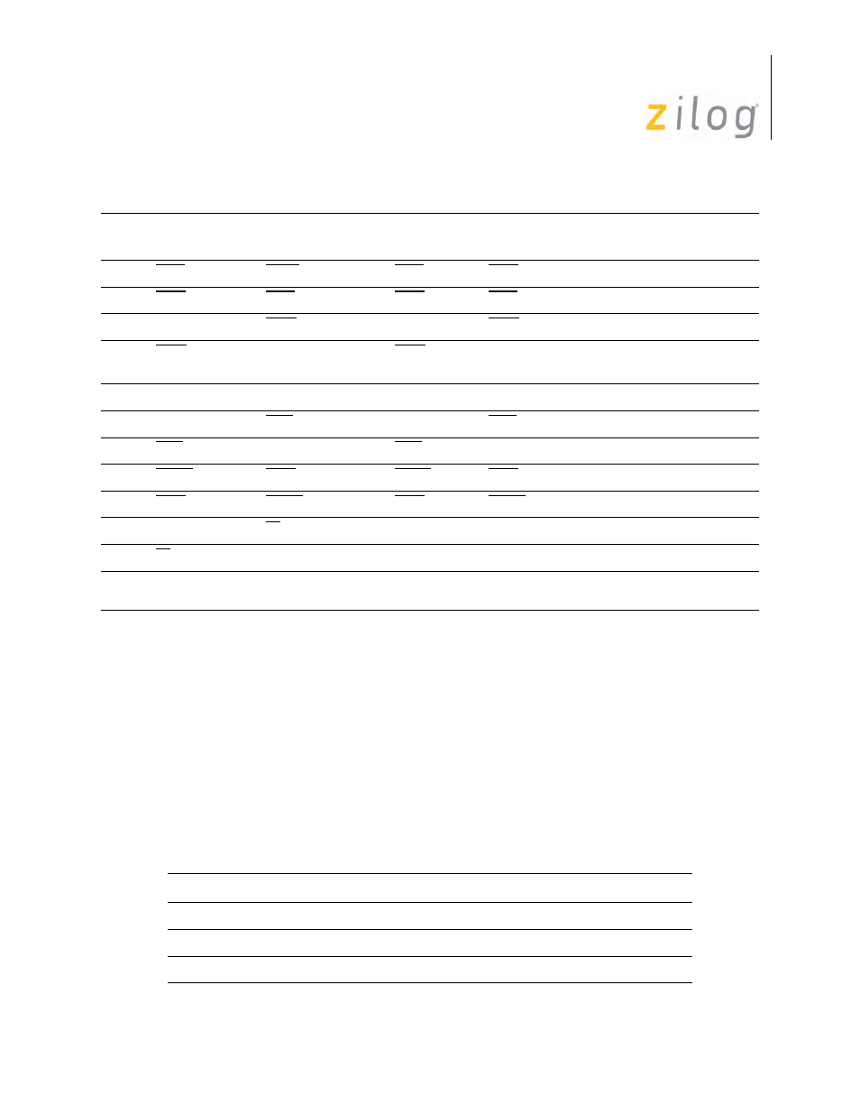
Comparison of the two previous tables leads to following conclusions:
•
Pins 1-5 can always be jumpered straight across from a J5-J10 connector block to a J13-
J15 connector block.
•
In a synchronous environment, the Transmit clock can be either driven or received and the
Receive clock can be received from the DTE connector or sent on the DCE connector.
The 10-pin J11 and J12 jumper blocks provide connections to the Port pins of the IUSC and
(M)USC, respectively. As with J5-J10, these connections may be to the customer’s off-board cus-
tom circuits and/or to certain pins in the J13-J15 blocks. The following pin assignment is deter-
mined so that if a 2-channel USC is plugged into the (M)USC socket, J12 has the same pin-out for
the USC’s B channel as do J5-J10 for other channels (see Table ).
5
DTR
DSR
DTR
DSR
Output to J1-J4
6
DSR
DTR
DSR
DTR
Input from J1-J4
7
DCD
DCD
Output to J1B, J2B, J3B
8
DCD
DCD
Input from J1A, J2A, J3A,
J4
10
GND
GND
GND
GND
11
RxC
RxC
Output to J1B, J2B, J3B
12
RxC
RxC
Input from J1A, J2A, J3A
13
TxCO
TxCI
TxCO
TxCI
Output to J1-3
14
TxCI
TxCO
TxCI
TxCO
Input from J1-3
(NOTE)
15
RI
Output to J1B, J2B
16
RI
Input from J1A, J2A
Note:
Various conventions are used to combine synchronous clock inputs and modem control inputson Apple
Macintosh connectors similar to J4, as described in the later section.
Pin Assignments of Controller Port Connectors
Pin No
J11:IUSC Signal
J12: (M)USC Signal
1
Port1(Clock 1 In)
Port1
2
Port4 (Xmit TSA Gate Out)
Port4 (Xmit TSA Gate Out)
3
N/C
N/C
Pin Assignments of Line Driver/Receiver Connectors (Continued)
Pins
J13-J14
DTE Signal
J13-J14
DCE Signal
J15
DTE Signal
J15
DCE Signal Direction/Where Used