Dpll operation in the fm modes – Zilog Z80230 User Manual
Page 88
SCC/ESCC
User Manual
UM010903-0515
SCC/ESCC Ancillary Support Circuitry
81
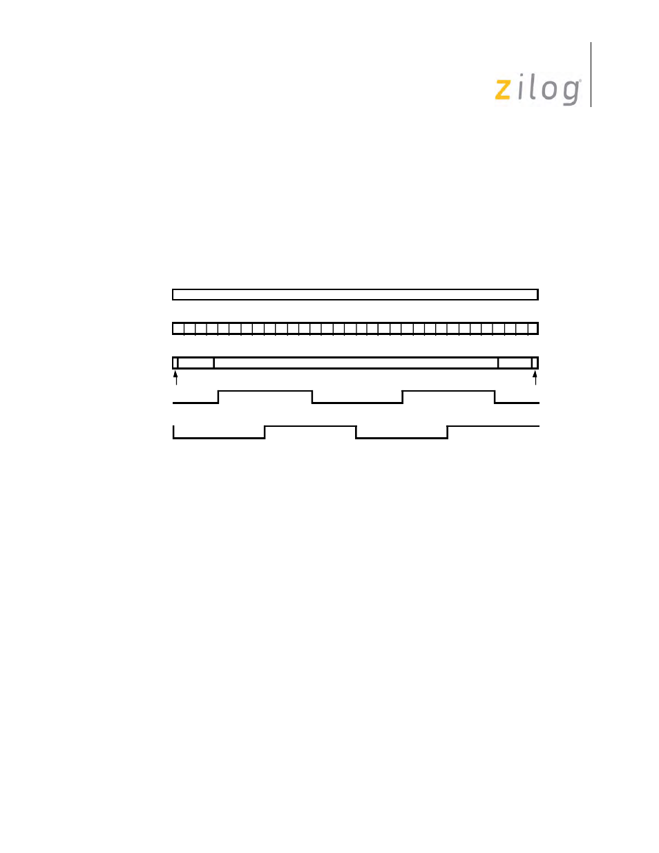
DPLL Operation in the FM Modes
To operate in FM mode, the DPLL must be supplied with a clock that is 16 times the data rate. The
DPLL uses this clock, along with the receive data, to construct, receive, and transmit clock outputs
that are phased to receive and transmit data properly.
In FM mode, the counter in the DPLL counts from 0 to 31, but now each cycle corresponds to 2-bit
cells. To make adjustments to remain in phase with the receive data, the DPLL divides a pair of bit
cells into five regions, making the adjustment to the counter dependent upon which region the
transition on the receive data input occurred (
).
DPLL Operation in the FM Mode
In FM mode, the transmit clock and receive clock outputs from the DPLL are not in phase. This is
necessary to make the transmit and receive bit cell boundaries coincide, since the receive clock
must sample the data one-fourth and three-fourths of the way through the bit cell.
Ordinarily, a bit cell boundary occurs between count 15 or count 16, and the DPLL receive output
causes the data to be sampled at one-fourth and three-fourths of the way through the bit cell.
However, four variations can occur:
If the bit-cell boundary (from space to mark) occurs anywhere during the second half of count 15
or the first half of count 16, the DPLL allows the transition without making a correction to its
count cycle.
If the bit-cell boundary (from space to mark) occurs between the middle of count 16 and the mid-
dle of count 19, the DPLL is sampling the data too early in the bit cell. In response to this, the
DPLL extends its count by one during the next 0 to 31 counting cycle, which effectively moves the
receive clock edges closer to where they should be.
Any transitions occurring between the middle of count 19 in one cycle and the middle of count 12
during the next cycle are ignored by the DPLL. This guarantees that any data transitions in the bit
cells do not cause an adjustment to the counting cycle.
1
18 19 20
17
16
21 22 23 24 25 26 27 28 29 30 31
2 3 4 5
7 8 9
12 13 14
11
10
15
0
No Change
No Change
Bit Cell
Count
Correction
RX DPLL Out
+1
Ignored
6
+1
TX DPLL Out