Network requirements – H3C Technologies H3C SecPath F1000-E User Manual
Page 113
Advertising
23
Figure 25 Create a Layer 2 static aggregation group on Device B
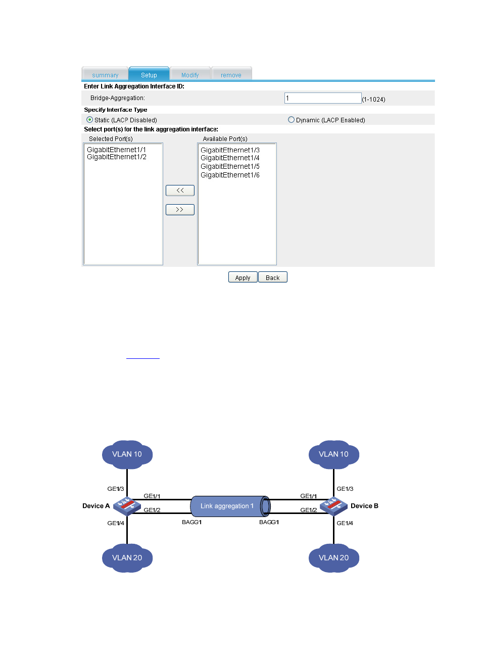
Layer 2 Dynamic Link Aggregation Configuration Example
Network requirements
As shown in
:
•
Device A and Device B are connected through their respective Layer 2 Ethernet interfaces
GigabitEthernet 1/1 through GigabitEthernet 1/2.
•
Configure a Layer 2 dynamic aggregation group on Device A and Device B to enable
communication between VLAN 10 at both ends of the aggregate link and between VLAN 20 at
both ends of the aggregate link.
Figure 26 Network diagram for Layer 2 dynamic link aggregation
Advertising
This manual is related to the following products: