Basic concepts in mstp, Mst region – H3C Technologies H3C SecPath F1000-E User Manual
Page 203
10
Basic Concepts in MSTP
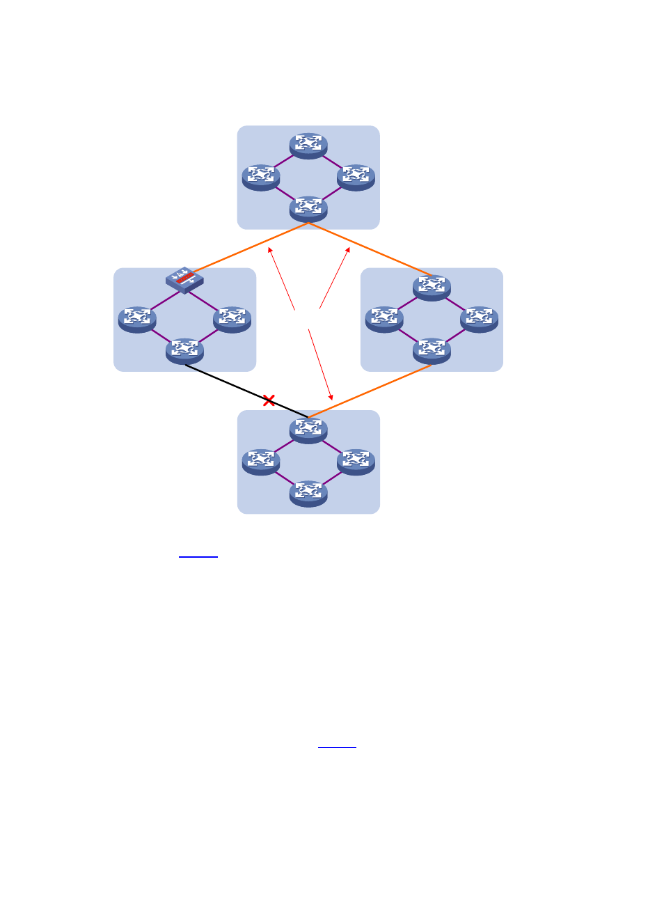
Figure 4 Basic concepts in MSTP
CST
Region A0
VLAN 1 mapped to instance 1
VLAN 2 mapped to instance 2
Other VLANs mapped to CIST
Region B0
VLAN 1 mapped to instance 1
VLAN 2 mapped to instance 2
Other VLANs mapped to CIST
Region C0
VLAN 1 mapped to instance 1
VLAN 2 and VLAN 3 mapped to
instance 2
Other VLANs mapped to CIST
Region D0
VLAN 1 mapped to instance 1,
B serving as the regional root
bridge
VLAN 2 mapped to instance 2,
C serving as the regional root
bridge
Other VLANs mapped to CIST
BPDU
BPDU
BPDU
C
D
B
A
All devices in
are running MSTP. This section explains some basic concepts of MSTP based on
the figure.
MST region
A multiple spanning tree region (MST region) consists of multiple devices in a switched network and the
network segments among them. These devices have the following characteristics:
•
All are MSTP-enabled,
•
They have the same region name,
•
They have the same VLAN-to-MSTI mapping configuration,
•
They have the same MSTP revision level configuration, and
•
They are physically linked with one another.
For example, all the devices in region A0 in
have the same MST region configuration as follows:
•
The same region name,
•
The same VLAN-to-MSTI mapping configuration (VLAN 1 is mapped to MSTI 1, VLAN 2 to MSTI 2,
and the rest to the common and internal spanning tree (CIST, that is, MSTI 0), and
•
The same MSTP revision level (not shown in the figure).