Inbound link load balancing configuration example, Network requirements, Configuration considerations – H3C Technologies H3C SecPath F1000-E User Manual
Page 917
52
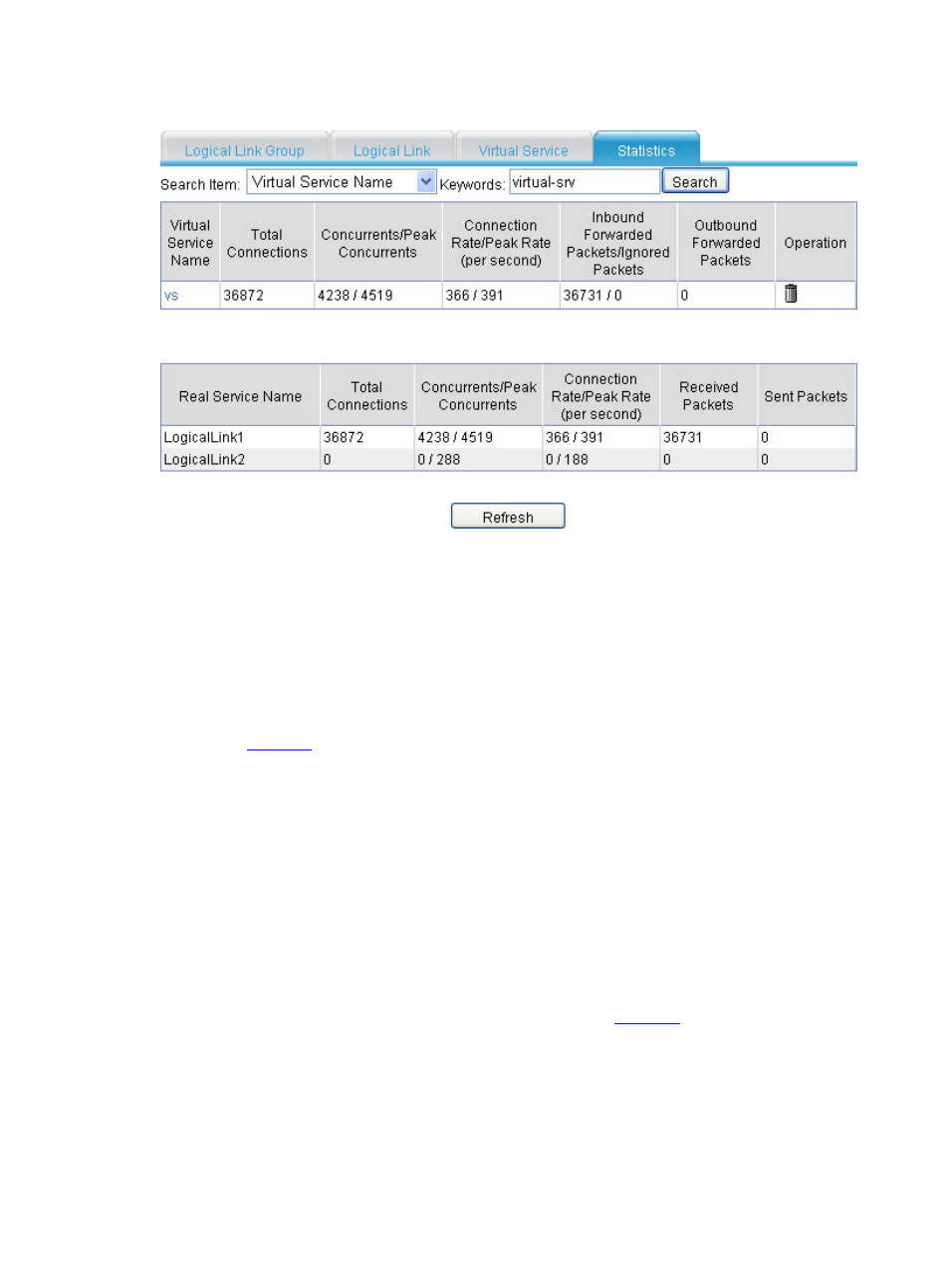
Figure 58 Statistics (II)
The above information indicates that packets destined to 10.2.0.0/24 are distributed to the optimal link
ISP2, and packets destined to 10.66.3.0/24 are distributed to link ISP1, and the outbound link load
balancing function has taken effect.
Inbound Link Load Balancing Configuration Example
Network requirements
As shown in
, Server (with the domain name whatever.com.cn) provides Web services through
two rent physical links ISP 1 and ISP 2. The router hops, bandwidth and cost of the two links are the same,
but the network delay of ISP 2 is smaller than that of ISP 1. It is hoped that users that correspond to local
DNS server B use physical link 1 and users corresponding to local DNS server A use the optimal link
between the two links.
Configuration considerations
•
Inbound link load balancing is required.
•
Packets are transmitted to the destination over the best link. Best performing link detection is
adopted.
•
DNS requests with the source IP address 10.66.3.1/24 are transmitted over physical link ISP 1: ACL
is used.
Based on the above analysis, the networking scheme as shown in
is used.