Yaskawa Sigma-5 User Manual: Design and Maintenance - Rotary Motors - Analog Voltage and Pulse Train Reference User Manual
Page 103
4.3 Trial Operation for Servomotor without Load from Host Reference
4-5
4
Tri
al Op
eration
4.3.1 Inspecting Connection and Status of Input Signals
Check the items in step 1 before trial operation of the servomotor under speed control and position control ref-
erences from the host controller.
Check the connection and status of input signals using the following procedure.
Step
Operation
Reference
1
Connect the necessary input signals to the I/O signal connector (CN1) under the following con-
ditions.
• It must be possible to input servo ON signal (/S-ON).
• The forward run prohibited (P-OT) and reverse run prohibited (N-OT) input signals must be
ON (L level) (i.e., the servomotor must be able to run in forward and reverse).
Settings: CN1-42 and CN1-43 must be ON (low) or Pn50A.3 and Pn50B.0 must be set to 8 to
disable the forward and reverse run prohibited function.
Note:
• Return the settings to the previous ones after completing trial operation.
• Make sure that there is no reference input.
• If Pn002.2 is set to 1, the absolute encoder can temporarily be used as an incremental encoder,
which makes it possible to perform trial operation of the servomotor without Fn008 and SEN
signal settings.
Connect a safety function device to CN8 when using the safety function.
For the connecting method, refer to (1) Connecting a Safety Function Device.
Refer to the following connec-
tion diagrams.
3.2.3 Example of I/O Signal
Connections in Speed Control
3.2.4 Example of I/O Signal
Connections in Position Con-
trol
3.2.5 Example of I/O Signal
Connections in Torque Control
5.9 Absolute Encoders
5.11 Safety Function
3.2.2 Safety Function Signal
(CN8) Names and Functions
2
Connect the connector of the host controller to the I/O signal connector (CN1).
3
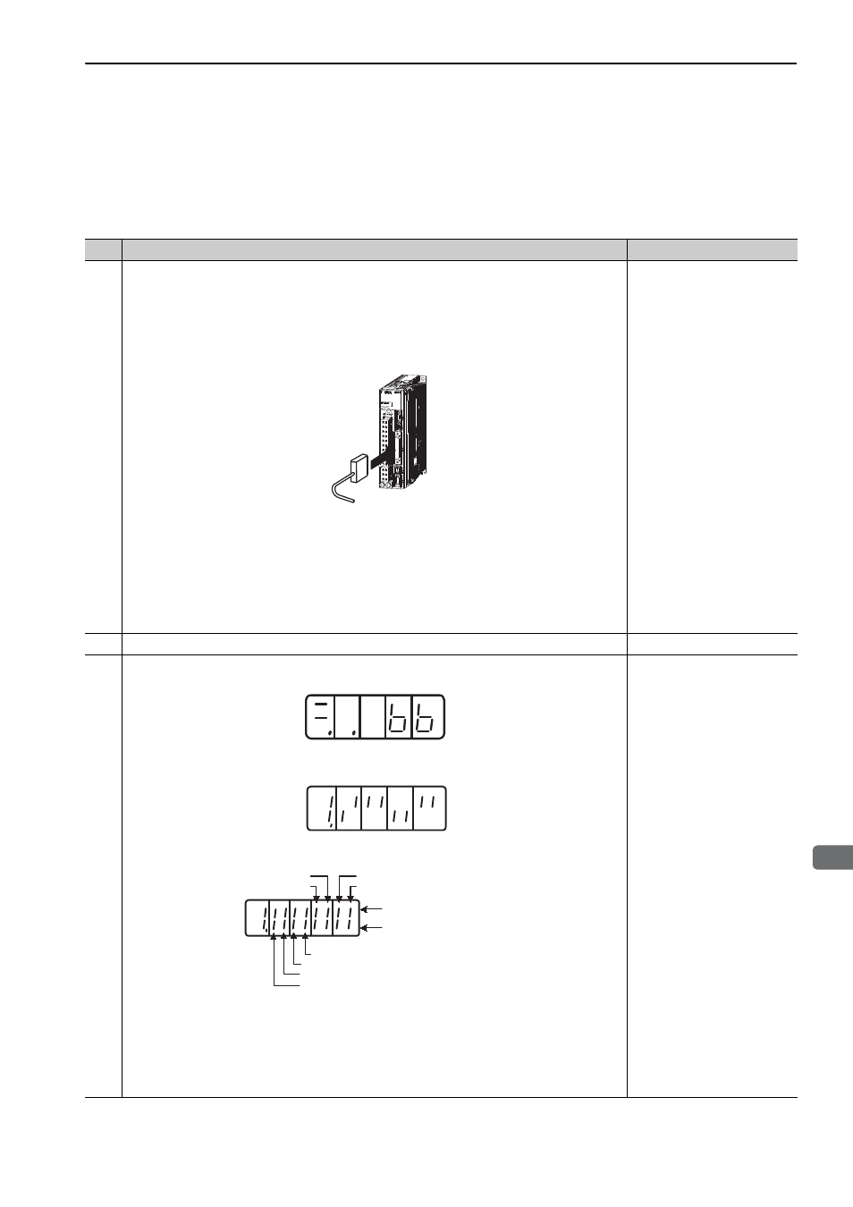
Turn ON the SERVOPACK power and make sure that the panel operator display is as shown
below.
Check the input signal using the input signal monitor (Un005) from the panel operator. If the dis-
play is not the same as shown below, correct the input signal setting.
Note:
• If an absolute encoder is being used, turn ON the SEN signal. The servomotor will not turn
ON when only the servo ON signal (/S-ON) is input.
• When the SEN signal is checked using the monitor display, the top of the LED will light
because the SEN signal is high when ON.
• Input signals can be also checked using wiring check function of SigmaWin+.
8.4 Monitoring Input Signals
3.3.1 Input Signal Allocations
CN1
Input signal LED display
/P-CL
/N-CL
Top lights when input
signal is high level.
Bottom lights when input
signal is low level.
/ALM-RST
/P-CON
/S-ON
P-OT
N-OT
SEN