Yaskawa Sigma-5 User Manual: Design and Maintenance - Rotary Motors - Analog Voltage and Pulse Train Reference User Manual
Page 366
10.1 Alarm Displays
10-19
10
Trou
blesh
ooting
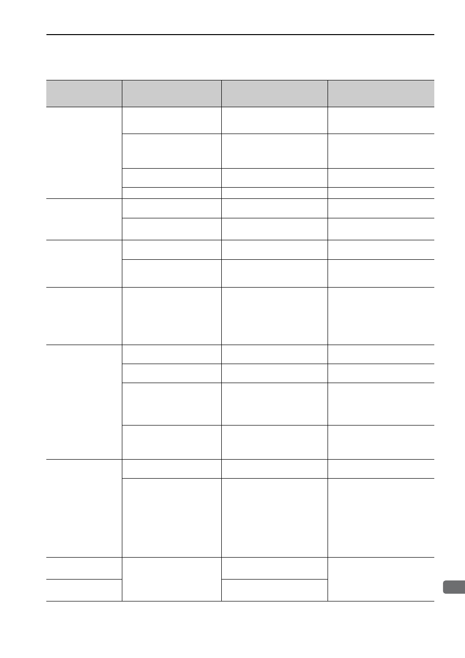
A.E72:
Feedback Option
Module Detection
Failure
The connection between the
SERVOPACK and the Feedback
Option Module is Faulty.
Check the connection between the
SERVOPACK and the Feedback
Option Module.
Correctly connect the Feedback
Option Module.
The Feedback Option Module
was disconnected.
−
Execute resetting configuration
error in option modules (Fn014) and
turn the power supply OFF and then
ON again.
A Feedback Option Module fault
occurred.
−
Replace the Feedback Option Mod-
ule.
A SERVOPACK fault occurred.
−
Replace the SERVOPACK.
A.E74:
Unsupported Safety
Option Module
A safety option module fault
occurred.
−
Replace the safety option module.
A unsupported safety option
module was connected.
Refer to the catalog of the con-
nected safety option module.
Connect a compatible safety option
module.
A.E75:
Unsupported Feed-
back Option Module
A feedback option module fault
occurred.
−
Replace the feedback option mod-
ule.
A unsupported feedback option
module was connected.
Refer to the catalog of the con-
nected feedback option module or
the manual of the SERVOPACK.
Connect a compatible feedback
option module.
A.Eb1:
Safety Function Signal
Input Timing Error
The lag between activations of
the input signals /HWBB1 and
/HWBB2 for the HWBB function
is ten second or more.
Measure the time lag between the /
HWBB1 and
/HWBB2 signals.
The output signal circuits or devices
for /HWBB1 and /HWBB2 or the
SERVOPACK input signal circuits
may be faulty. Alternatively, the
input signal cables may be discon-
nected. Check if any of these items
are faulty or have been disconnected.
A.F10:
Main Circuit Cable
Open Phase
(With the main power
supply ON, voltage was
low for more than 1 sec-
ond in an R, S, or T
phase.)
(Detected when the main
power supply was turned
ON.)
The three-phase power supply
wiring is incorrect.
Check the power supply wiring.
Confirm that the power supply is
correctly wired.
The three-phase power supply is
unbalanced.
Measure the voltage at each phase
of the three-phase power supply.
Balance the power supply by chang-
ing phases.
A single-phase power is input
without setting Pn00B.2 (power
supply method for three-phase
SERVOPACK) to 1 (single-phase
power supply).
Check the power supply and the
parameter setting.
Match the parameter setting to the
power supply.
A SERVOPACK fault occurred.
−
Turn the power supply OFF and
then ON again. If the alarm still
occurs, the SERVOPACK may be
faulty. Replace the SERVOPACK.
A.F50:
Servomotor Main
Circuit Cable
Disconnection
(The servomotor did not
operate or power was not
supplied to the servomo-
tor even though the /S-
ON (Servo ON) signal
was input when the ser-
vomotor was ready to
receive it.)
A SERVOPACK fault occurred.
−
The SERVOPACK may be faulty.
Replace the SERVOPACK.
The wiring is not correct or there
is a faulty contact in the motor
wiring.
Check the wiring.
Make sure that the servomotor is
correctly wired.
FL-1
*2
:
System Alarm
SERVOPACK failure
−
Turn the power supply OFF and
then ON again. If the alarm still
occurs, the SERVOPACK may be
faulty. Replace the SERVOPACK.
FL-2
*2
:
System Alarm
−
(cont’d)
Alarm Number:
Alarm Name
(Alarm Description)
Cause
Investigative Actions
Corrective Actions