18 (3) serial data specifications, 4) transferring alarm contents – Yaskawa Sigma-5 User Manual: Design and Maintenance - Rotary Motors - Analog Voltage and Pulse Train Reference User Manual
Page 344
9 Fully-closed Loop Control
9.3.4 External Absolute Encoder Data Reception Sequence
9-18
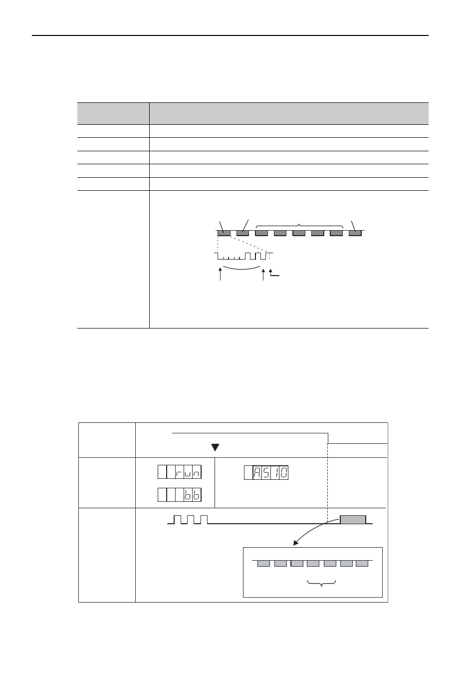
(3) Serial Data Specifications
The serial data is output from the PAO signal.
(4) Transferring Alarm Contents
If an external absolute encoder is used, the contents of alarms detected by the SERVOPACK are transmitted in
serial data to the host controller from the PAO output when the SEN signal changes from high level to low
level.
Note: The SEN signal cannot be OFF while the servomotor power is ON.
Output example of alarm contents are as shown below.
Data Transfer
Method
Start-stop Synchronization (ASYNC)
Baud rate
9600 bps
Start bits
1 bit
Stop bits
1 bit
Parity
Even
Character code
ASCII 7-bit code
Data format
8 characters, as shown below.
Note: 1. Data is "P+00000" (CR) or "P-00000" (CR) when the position is zero.
2. The serial data range is "-32768" to "+32767". When this range is exceeded, the data
changes from "+32767" to "-32678" or from "-32768" to "+32767." When changing
multiturn limit, the range changes. For details, refer to 5.9.6 Multiturn Limit Setting.
Data
Start bit
Even parity
serial data
in five digits
"+" or " - "
"0" to "9"
"CR"
"P"
Stop bit
0 0 0 0 0 1 0 1 0 1
“A” “L” “M” “5” “1” “.” “CR”
Low level
High level
Error detection
or
Overspeed
Incremental pulse
Serial Data
Enlarged view
SEN Signal
Panel Operator
Display
PAO Output
Data Format
Upper 2 digits
45