Yaskawa Sigma-5 User Manual: Design and Maintenance - Rotary Motors - Analog Voltage and Pulse Train Reference User Manual
Page 65
3 Wiring and Connection
3.1.3 Using the SERVOPACK with Single-phase, 200 V Power Input
3-14
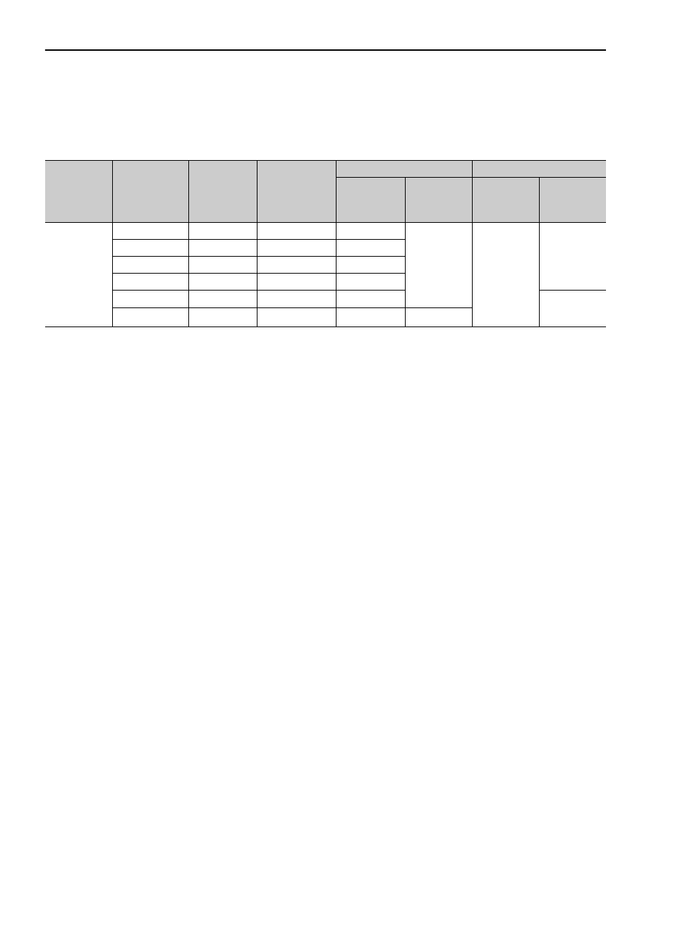
(6) How to Select Molded-case Circuit Breaker and Fuse Capacities
The following table shows the SERVOPACK’s current capacities and inrush current when using single-phase
200 V power supply. Select a molded-case circuit breaker and fuses in accordance with these specifications.
∗ The official model number is SGDV-120A01A008000.
Note 1. To comply with the EU low voltage directive, connect a fuse to the input side as protection against accidents
caused by short-circuits. Select the fuse for the input side that are compliant with UL standards.
The table above also provides the net values of current capacity and inrush current. Select a fuse and a molded-
case circuit breaker which meet the breaking characteristics shown below.
•Main circuit, control circuit: No breaking at three times the current values shown in the table for 5 s.
•Inrush current: No breaking at the current values shown in the table for 20 ms.
2. The following restrictions apply to UL standard compliance conditions for SGDV-120A01A008000 SERVO-
PACKs.
Current rating when using molded-case circuit breaker: 40 A max.
Main Circuit
Power Sup-
ply
Maximum
Applicable Ser-
vomotor
Capacity
[kW]
SERVO-
PACK Model
SGDV-
Power Supply
Capacity per
SERVOPACK
[kVA]
Current Capacity
Inrush Current
Main Circuit
[Arms]
Control Cir-
cuit
[Arms]
Main Circuit
[A0-p]
Control Cir-
cuit
[A0-p]
Single-phase,
200 V
0.05
R70A 0.2
2
0.2
33
70
0.1
R90A 0.3
2
0.2
1R6A 0.7
3
0.4
2R8A
1.2
5
0.75
5R5A
1.9
9
33
1.5
120A
*
4
16
0.25