Yaskawa Sigma-5 User Manual: Design and Maintenance - Rotary Motors - Analog Voltage and Pulse Train Reference User Manual
Page 74
3.2 I/O Signal Connections
3-23
3
Wi
ring an
d Conn
ecti
on
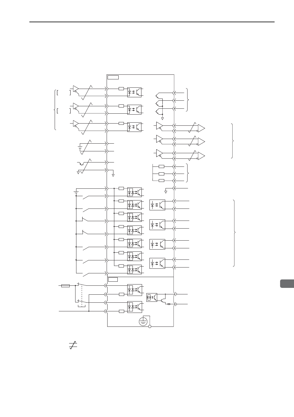
3.2.4 Example of I/O Signal Connections in Position Control
Connection example in position control is as shown below.
∗1.
represents twisted-pair wires.
∗2. Connect when using an absolute encoder. When the encoder cable with the battery case is connected, do not connect
a backup battery.
∗3. The 24-VDC power supply is not included. Use a 24-VDC power supply with double insulation or reinforced insula-
tion.
∗4. When using the safety function, a safety function device must be connected and the wiring that is necessary to acti-
vate the safety function must be done to turn ON the servomotor power. When not using the safety function, use the
SERVOPACK with the JZSP-CVH05-E Plug (provided as an accessory) inserted into the CN8.
∗5. Always use line receivers to receive the output signals.
2
+5 V
0 V
SEN
SG
BAT(+)
BAT(-)
ALO1
ALO2
ALO3
PBO
PCO
/PBO
PAO
/PAO
/PCO
/COIN+
/COIN-
/TGON+
/TGON-
/S-RDY+
ALM+
ALM-
4
22
21
27
28
29
30
31
32
26
25
19
33
34
35
36
20
3
18
13
37
38
39
+24 V
+24 VIN
3.3 k
Ω
/S-ON
/P-CON
P-OT
N-OT
/ALM-RST
/N-CL
47
+12 V
41
43
42
44
45
/P-CL
46
40
/S-RDY-
PL1
PL2
PL3
1
SG
FG
/HWBB1+
/HWBB1-
/HWBB2+
/HWBB2-
6
3
4
5
EDM1+
EDM1-
/PULS
SIGN
/SIGN
PULS
1.0 k
Ω
1.0 k
Ω
1.0 k
Ω
CN8
CN1
8
7
14
15
150
Ω
CLR
/CLR
12
11
150
Ω
8
7
150
Ω
*3
PULS
SIGN
CLR
SERVOPACK
Alarm code output (OFF for alarm)
Max. operating voltage: 30 VDC
Max. output current: 20 mA DC
Servo ON
(Servo ON when ON)
Reverse run prohibited
(Prohibited when OFF)
Forward run prohibited
(Prohibited when OFF)
Alarm reset
(Reset when ON)
Reverse external torque limit
(Limit when ON)
Forward external torque limit
(Limit when ON)
SEN signal input
Backup battery
2.8 to 4.5 V
*2
*2
P control
(P control when ON)
Positioning completed
(ON when positioning
completes.)
Rotation Detection output
(ON when the motor speed
exceeds the settings.)
Servo ready output
(ON when ready)
Servo alarm output
(OFF for an alarm)
Photocoupler output
Max. operating voltage:
30 VDC
Max. output current:
50 mA DC
Position
reference
CW
Phase A
CCW
Phase B
*1
Connect shield to
connector shell.
Switch
Fuse
24 V
0 V
Safety function device
*4
Power supply for
open-collector output reference
Connector
shell
SERVOPACK
Applicable line receiver:
SN75ALS175 or
MC3486 manufactured
by Texas Instruments or
the equivalent
Encoder output
pulse phase A
Encoder output
pulse phase B
Encoder output
pulse phase C
*5
*5
*5
45