Yaskawa Sigma-5 User Manual: Design and Maintenance - Rotary Motors - Analog Voltage and Pulse Train Reference User Manual
Page 405
11.2 List of Parameters
11-29
11
Ap
pend
ix
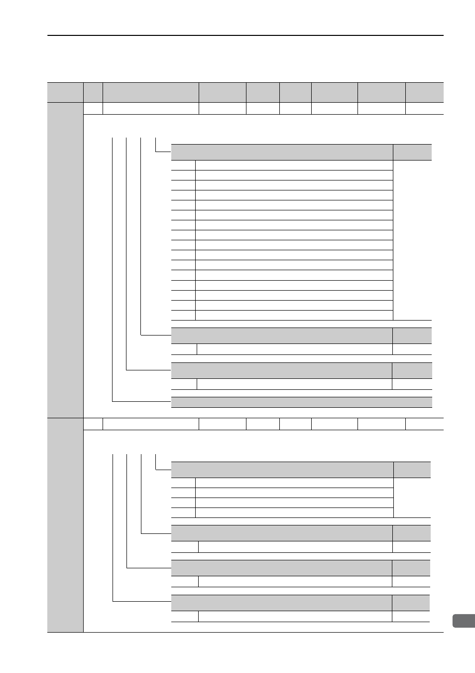
Pn50D
2
Input Signal Selection 4
0000 to FFFF
−
8888
After restart
Setup
−
Pn50E
2
Output Signal Selection 1
0000 to 3333
−
3211
After restart
Setup
−
(cont’d)
Parameter
No.
Size
Name
Setting
Range
Units
Factory
Setting
When
Enabled
Classification
Reference
Section
/ZCLAMP Signal Mapping (Zero clamp when ON (closed))
Reference
Section
0
Active when CN1-40 input signal is ON (closed).
5.3.5
1
Active when CN1-41 input signal is ON (closed).
2
Active when CN1-42 input signal is ON (closed).
3
Active when CN1-43 input signal is ON (closed).
4
Active when CN1-44 input signal is ON (closed).
5
Active when CN1-45 input signal is ON (closed).
6
Active when CN1-46 input signal is ON (closed).
7
Always active (fixed).
8
Not active (fixed).
9
Active when CN1-40 input signal is OFF (open).
A
Active when CN1-41 input signal is OFF (open).
B
Active when CN1-42 input signal is OFF (open).
C
Active when CN1-43 input signal is OFF (open).
D
Active when CN1-44 input signal is OFF (open).
E
Active when CN1-45 input signal is OFF (open).
F
Active when CN1-46 input signal is OFF (open).
/INHIBIT Signal Mapping (Reference pulse inhibit when ON (closed))
Reference
Section
0 to F
Same as /ZCLAMP Signal Mapping.
5.4.8
/G-SEL1 Signal Mapping (Gain change when ON (closed))
Reference
Section
0 to F
Same as /ZCLAMP Signal Mapping.
6.9.6
Reserved (Do not change.)
4th 3rd 2nd 1st
digit digit digit digit
n.
Positioning Completion Signal Mapping (/COIN)
Reference
Section
0
Disabled (the above signal is not used.)
5.4.6
1
Outputs the signal from CN1-25, -26 output terminal.
2
Outputs the signal from CN1-27, -28 output terminal.
3
Outputs the signal from CN1-29, -30 output terminal.
Speed Coincidence Detection Signal Mapping (/V-CMP)
Reference
Section
0 to 3
Same as /COIN Signal Mapping.
5.3.8
Servomotor Rotation Detection Signal Mapping (/TGON)
Reference
Section
0 to 3
Same as /COIN Signal Mapping.
5.10.3
Servo Ready Signal Mapping (/S-RDY)
Reference
Section
0 to 3
Same as /COIN Signal Mapping.
5.10.4
4th 3rd 2nd 1st
digit digit digit digit
n.