5 using more than one servopack, 1) wiring example, 2) precautions – Yaskawa Sigma-5 User Manual: Design and Maintenance - Rotary Motors - Analog Voltage and Pulse Train Reference User Manual
Page 68: Analog
3.1 Main Circuit Wiring
3-17
3
Wi
ring an
d Conn
ecti
on
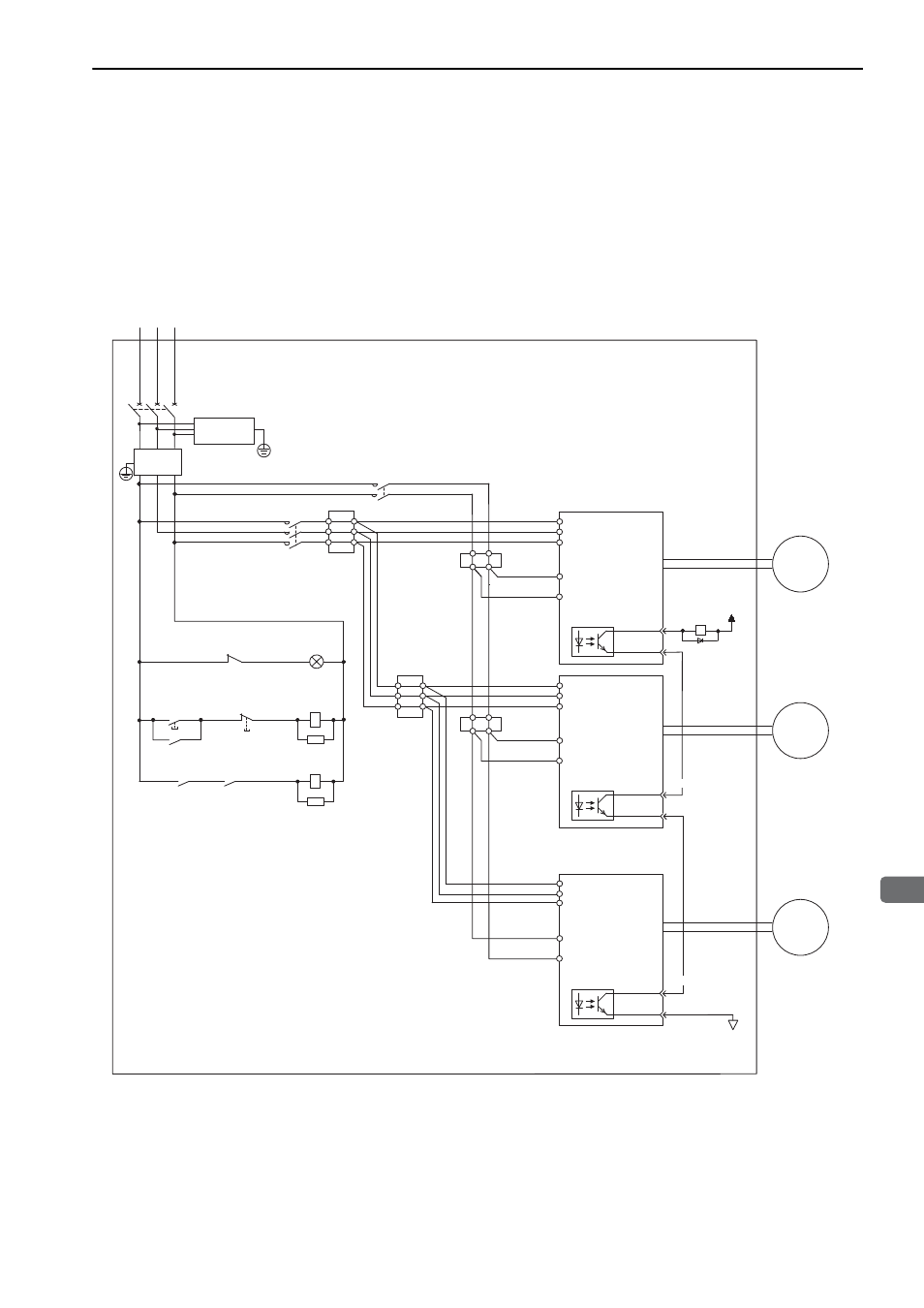
3.1.5 Using More Than One SERVOPACK
This section shows an example of the wiring and the precautions when more than one SERVOPACK is used.
(1) Wiring Example
Connect the alarm output (ALM) terminals for three SERVOPACKs in series to enable alarm detection relay
1RY to operate. When the alarm occurs, the ALM output signal transistor is turned OFF.
(2) Precautions
Multiple SERVOPACKs can share a single molded-case circuit breaker (1QF) or noise filter. Always select a
molded-case circuit breaker or noise filter that has enough capacity for the total power supply capacity (load
conditions) of the SERVOPACKs.
R S
T
1QF
2KM
1Ry
+24 V
L1
L2
L3
L1C
0V
L2C
1FLT
M
L1
L2
L3
L1
L2
L3
L1C
1D
L2C
M
M
L1C
L2C
3SA
1KM
1PL
1KM
2KM
1SA
2SA
31
32
CN1
1KM
1Ry
1KM
ALM+
ALM
−
31
32
CN1
ALM
−
31
32
CN1
ALM
−
1Ry
ALM+
ALM+
SERVOPACK
Servomotor
Servomotor
Servomotor
Relay
terminal
Relay
terminal
Relay
terminal
1QF:
1FLT:
1KM: Magnetic contactor
(for control power supply)
2KM:
(for main circuit power supply)
1Ry:
1PL:
1SA:
2SA:
3SA:
1D:
Molded-case circuit breaker
Noise filter
Relay
Magnetic contactor
Indicator lamp
Surge absorber
SERVOPACK
SERVOPACK
Surge absorber
Surge absorber
Flywheel diode
supply ON
Power supply
Relay
terminal
(For servo alarm
display)
Servo power
supply OFF
Servo power
Analog