6 (1) connecting a safety function device, Analog – Yaskawa Sigma-5 User Manual: Design and Maintenance - Rotary Motors - Analog Voltage and Pulse Train Reference User Manual
Page 104
4 Trial Operation
4.3.1 Inspecting Connection and Status of Input Signals
4-6
(1) Connecting a Safety Function Device
There are two types of the safety function’s jumper connectors that are attached to SERVOPACKs. You must
remove the safety function’s jumper connector before connecting a safety function device. The connection
method depends on the connector type that is used. Read the following procedures well before you attach a
safety function device.
Use the following procedures to attach safety function devices.
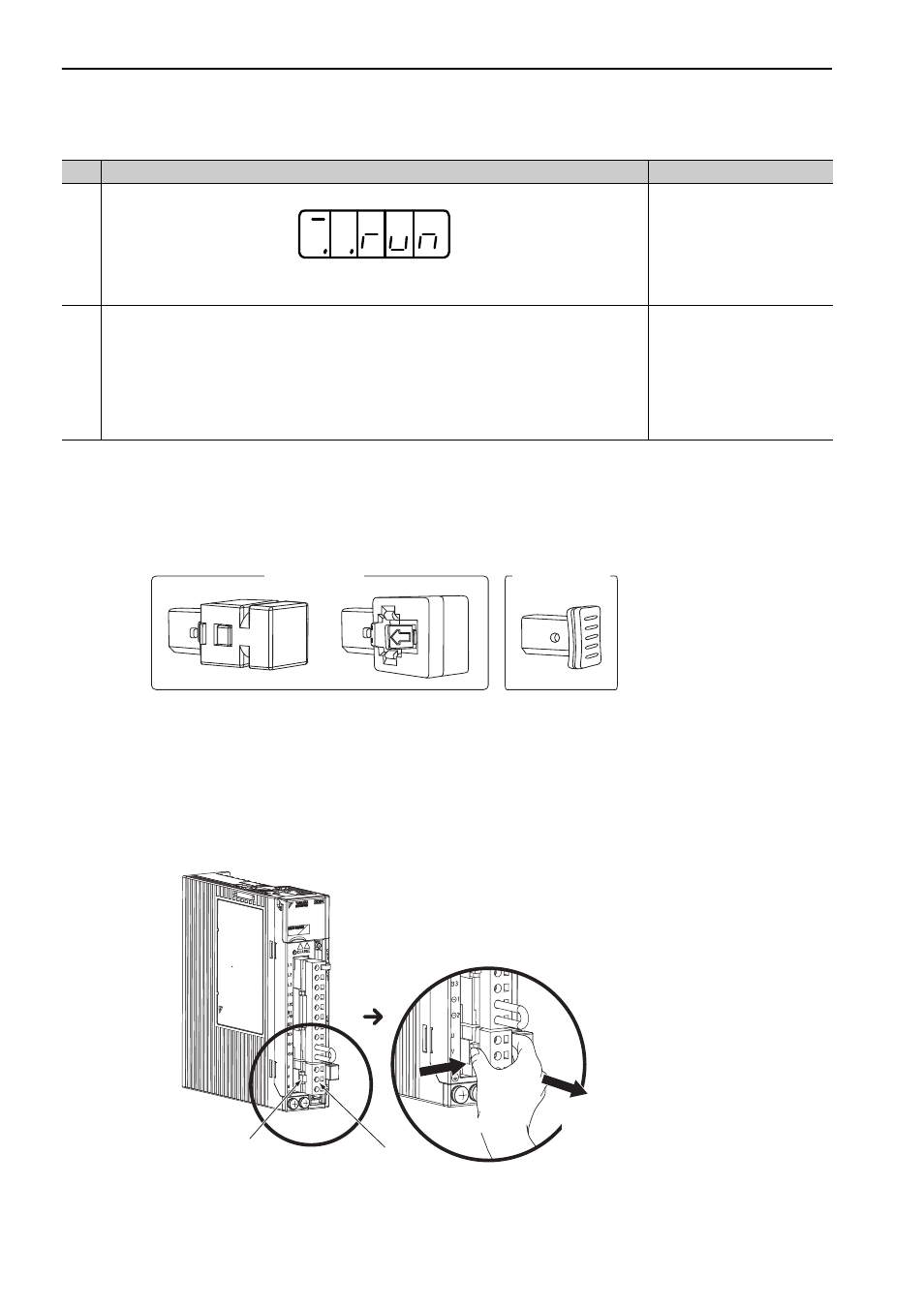
Connector Type A
1.
Remove the servomotor connection terminal connector while pressing the lock.
Applicable SERVOPACKs:
SGDV-R70F, -R90F, -2R1F, -R70A, -R90A, -1R6A, -2R8A, -1R9D, -3R5D, -5R4D
For SERVOPACK models not listed above, it is not necessary to remove the servomotor connection ter-
minal connector. Go to step 2.
4
Input the /S-ON signal, then make sure that the display of the panel operator is as shown below.
If an alarm display appears, correct it according to 10.1 Alarm Displays. If the cause of alarm is
not corrected, the servo ON signal cannot be input and the servomotor cannot be turned on.
10.1 Alarm Displays
5
This completes all preparations for trial operation. Perform trial operation in each control
method.
4.3.2 Trial Operation in Speed
Control
4.3.3 Trial Operation under
Position Control from the Host
Controller with the SERVO-
PACK Used for Speed Control
4.3.4 Trial Operation in Posi-
tion Control
(cont’d)
Step
Operation
Reference
Connector Type A
Connector Type B
Servomotor connection
terminal connector
Enlarged View
1. Press the lock.
Remove the servomotor
connection terminal connector
while pressing the lock.
Lock
2.
Analog