2 one-parameter tuning procedure, 1) panel operator operating procedure – Yaskawa Sigma-5 User Manual: Design and Maintenance - Rotary Motors - Analog Voltage and Pulse Train Reference User Manual
Page 242
6.5 One-parameter Tuning (Fn203)
6-39
6
Adjustm
e
nts
6.5.2 One-parameter Tuning Procedure
The following procedure is used for one-parameter tuning.
There are the following two operation procedures depending on the tuning mode being used.
• When the tuning mode is set to 0 or 1, the model following control will be disabled and one-parameter tun-
ing will be used as the tuning method for applications other than positioning.
• When the tuning mode is set to 2 or 3, the model following control will be enabled and it can be used for
tuning for positioning.
One-parameter tuning is performed from the panel operator, digital operator (option), or SigmaWin+.
Only tuning modes 0 and 1 can be selected from the panel operator. Make sure that the moment of inertia ratio
(Pn103) is set correctly using advance autotuning before beginning operation.
The following section provides the operating procedure from the panel operator and digital operator.
Refer to the
Σ
-V Series User’s Manual, Operation of Digital Operator (No.: SIEP S800000 55) for basic key
operations of the digital operator.
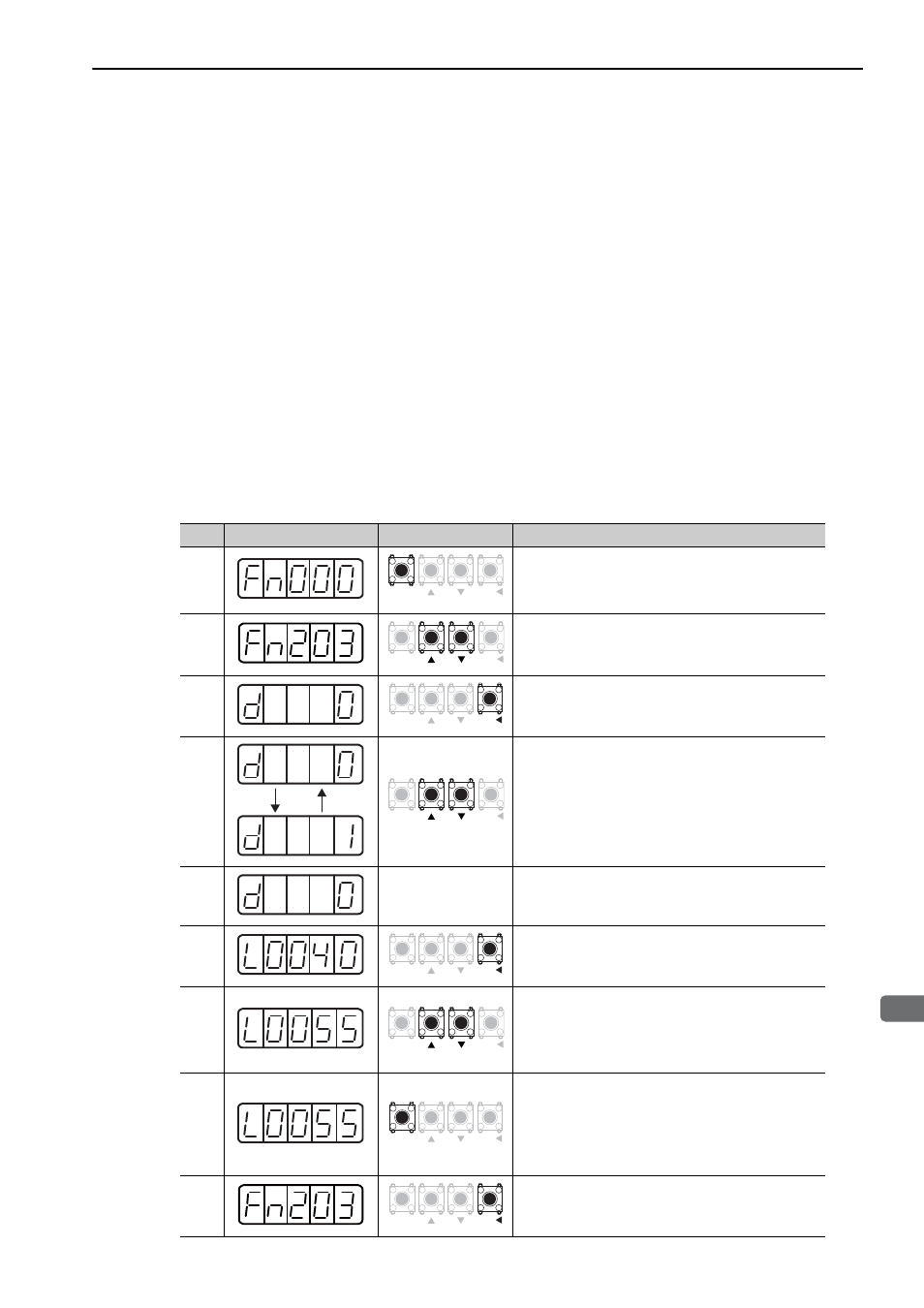
(1) Panel Operator Operating Procedure
Step Display after Operation
Keys
Operation
1
Press the MODE/SET Key to select the utility func-
tion mode.
2
Press the UP or DOWN Key to move through the list
and select Fn203.
3
Press the DATA/SHIFT Key for approximately one
second. The screen shown on the left will be dis-
played.
4
Press the UP or DOWN Key to move through the list
and select Tuning Mode.
TUNING MODE
0: Makes adjustments giving priority to stability.
1: Makes adjustments giving priority to responsive-
ness.
Note: TYPE (rigidity type) is fixed to 2.
5
If the servomotor power is OFF, input a servo ON
signal (/S-ON) from the host controller.
If the servomotor power is ON, go to step 6.
6
Press the DATA/SHIFT Key for less than one second.
The one parameter gain data shown on the left will be
displayed.
7
Press the UP or DOWN Key to change the one param-
eter gain value and change the actual servo gain
(Pn100, Pn101, Pn102, and Pn401) at the same time.
This tuning function terminates when you decide that
the response output is satisfactory.
8
Press the MODE/SET Key to save the calculated four
gains to the parameter. When tuning is finished,
“donE” will flash before returning to the screen shown
on the left.
Note: To end operation without saving the calculated
gain, go to step 9.
9
Press the DATA/SHIFT Key for approximately one
second. The display will return to Fn203.
MODE/SET
DATA/
MODE/SET
DATA/
MODE/SET
DATA/
MODE/SET
DATA/
MODE/SET
DATA/
MODE/SET
DATA/
MODE/SET
DATA/
MODE/SET
DATA/