Yaskawa Sigma-5 User Manual: Design and Maintenance - Rotary Motors - Analog Voltage and Pulse Train Reference User Manual
Page 171
5.7 Combination of Control Methods
5-57
5
Ope
rat
ion
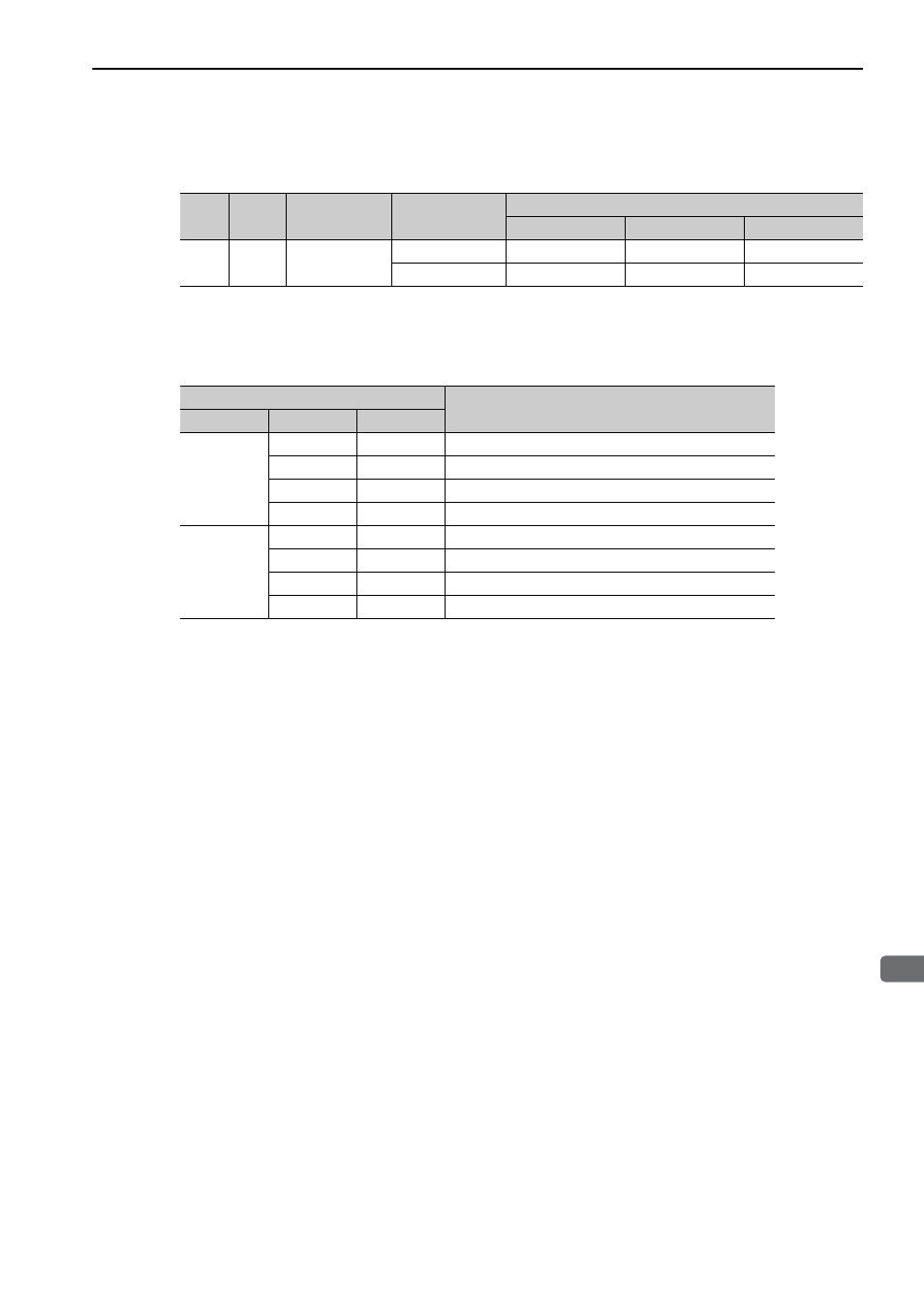
(2) Changing Input Signal Allocations (Pn50A.0 = 1)
The control method can be switched by turning the /C-SEL signal ON/OFF.
Note: Use parameter Pn50C.3 to allocate the /C-SEL signal for use. For details, refer to 3.3.1 Input Signal Allocations.
The following table shows the speed and direction in accordance with settings for the input signals for the set-
ting for internal set speed control when the /C-SEL signal is OFF.
Note: Use parameter Pn50C.0 to 2 to allocate the /SPD-D, /SPD-A, and /SPD-B signals for use. For details, refer to 3.3.1
Input Signal Allocations.
Type
Signal
Name
Connector
Pin Number
Setting
Pn000 Setting and Control Method
n.
4
n.
5
n.
6
Input
/C-SEL
Must be
allocated
ON (closed)
Speed
Position
Torque
OFF (open)
Internal set speed
Internal set speed
Internal set speed
Input Signal
Speed and Direction
/SPD-D
/SPD-A
/SPD-B
OFF
OFF
OFF
Stops at internal set speed 0.
OFF
ON
Forward rotation at internal set speed 1 set in Pn301.
ON
ON
Forward rotation at internal set speed 2 set in Pn302.
ON
OFF
Forward rotation at internal set speed 3 set in Pn303.
ON
OFF
OFF
Stops at internal set speed 0.
OFF
ON
Reverse rotation at internal set speed 1 set in Pn301.
ON
ON
Reverse rotation at internal set speed 2 set in Pn302.
ON
OFF
Reverse rotation at internal set speed 3 set in Pn303.