2) electronic gear ratio setting examples – Yaskawa Sigma-5 User Manual: Design and Maintenance - Rotary Motors - Analog Voltage and Pulse Train Reference User Manual
Page 155
5.4 Position Control
5-41
5
Ope
rat
ion
(2) Electronic Gear Ratio Setting Examples
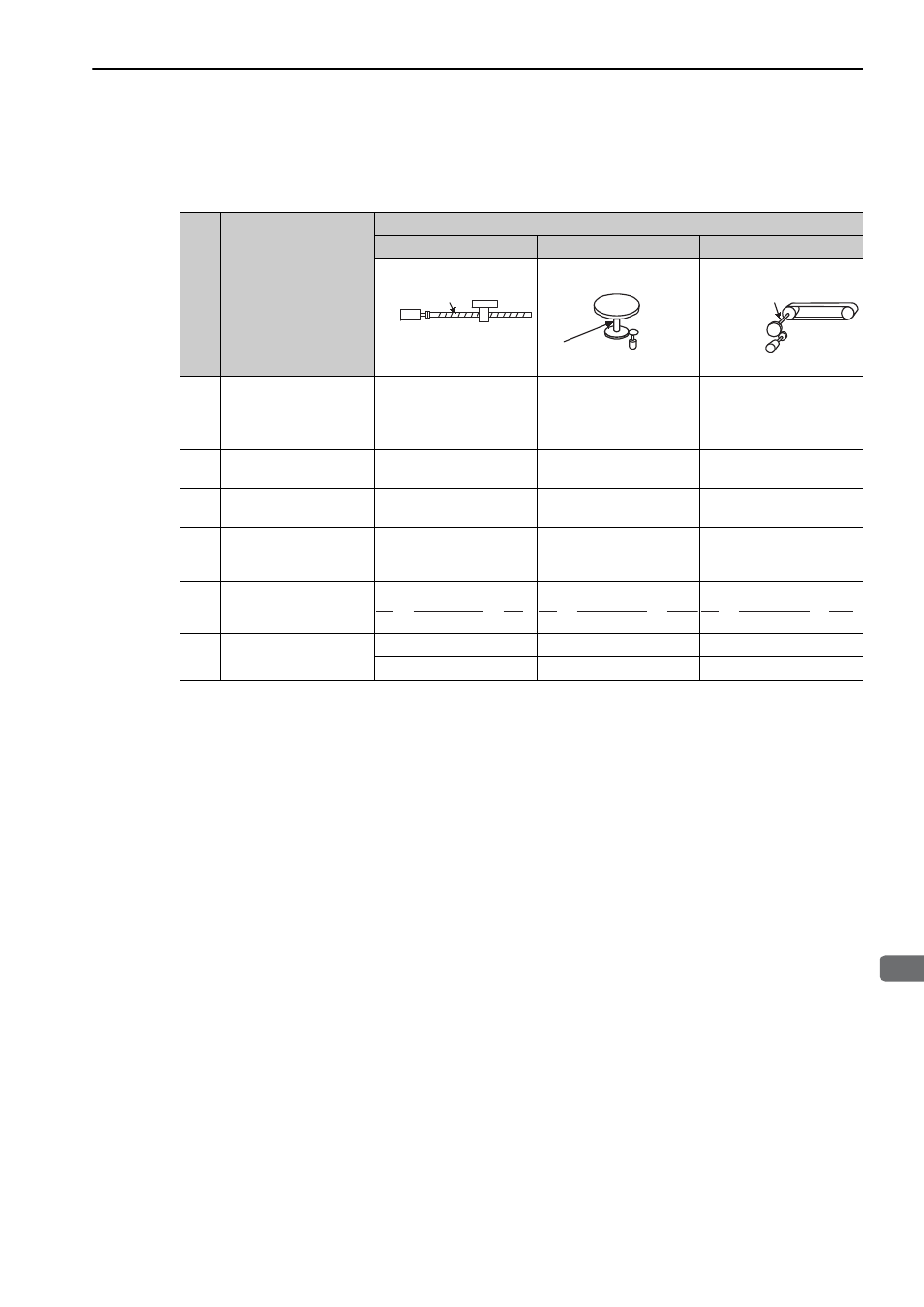
The following examples show electronic gear ratio settings for different load configurations.
Step
Operation
Load Configuration
Ball Screw
Disc Table
Belt and Pulley
1
Check machine specifica-
tions.
Ball screw pitch: 6 mm
Gear ratio: 1/1
Rotation angle per revolu-
tion: 360
°
Gear ratio: 1/100
Pulley diameter: 100 mm
(pulley circumference: 314
mm)
• Gear ratio: 1/50
2
Check the encoder reso-
lution.
1048576 (20-bit)
1048576 (20-bit)
1048576 (20-bit)
3
Determine the reference
unit used.
Reference unit: 0.001 mm
(1
μm)
Reference unit: 0.01
°
Reference unit: 0.005 mm
(5
μm)
4
Calculate the travel dis-
tance per load shaft revo-
lution. (Reference unit)
6 mm/0.001 mm=6000
360
°/0.01°=36000
314 mm/0.005 mm=62800
5
Calculate the electronic
gear ratio.
6
Set parameters.
Pn20E: 1048576
Pn20E: 104857600
Pn20E: 52428800
Pn210: 6000
Pn210: 36000
Pn210: 62800
Ball screw
pitch: 6 mm
20-bit encoder
Load shaft
Reference unit: 0.001 mm
20-bit encoder
Load shaft
Reference unit: 0.01
°
Gear ratio:
1/100
Load shaft
Gear ratio
1/50
Reference unit: 0.005 mm
Pulley diameter:
100 mm
20-bit encoder
1048576
6000
1
1
=
B
A
B
A
1048576
36000
100
1
=
B
A
1048576
62800
50
1
=