2) brake signal (/bk) setting – Yaskawa Sigma-5 User Manual: Design and Maintenance - Rotary Motors - Analog Voltage and Pulse Train Reference User Manual
Page 125
5.2 Basic Functions Settings
5-11
5
Ope
rat
ion
(2) Brake Signal (/BK) Setting
This output signal controls the brake. The output signal must be allocated with Pn50F. Refer to (3) Brake Sig-
nal (/BK) Allocation for allocation.
The /BK signal turns OFF (applies the brake) when an alarm is detected or the /S-ON signal is turned OFF.
The brake OFF timing can be adjusted with Pn506.
• Select the optimum surge absorber in accordance with the applied brake current and
brake power supply.
When using the LPSE-2H01-E power supply: Z10D471 (Made by SEMITEC
Corporation)
When using the LPDE-1H01-E power supply: Z10D271 (Made by SEMITEC
Corporation)
When using the 24-V power supply: Z15D121 (Made by SEMITEC Corporation)
• After the surge absorber is connected, check the total time the brake is applied for the
system. Depending on the surge absorber, the total time the brake is applied can be
changed.
• Configure the relay circuit to apply the holding brake by the emergency stop.
• The brake signal (/BK) cannot be used with factory settings. The output signal must
be allocated. Refer to (3) Brake Signal (/BK) Allocation to set the parameter Pn50F.
• When using a 24-V brake, separate the 24-VDC power supply from other power sup-
plies, such as the one used for the I/O signals of CN1 connectors. Always install the
24-VDC power supply separately. If the power supply is shared, the I/O signals might
malfunction.
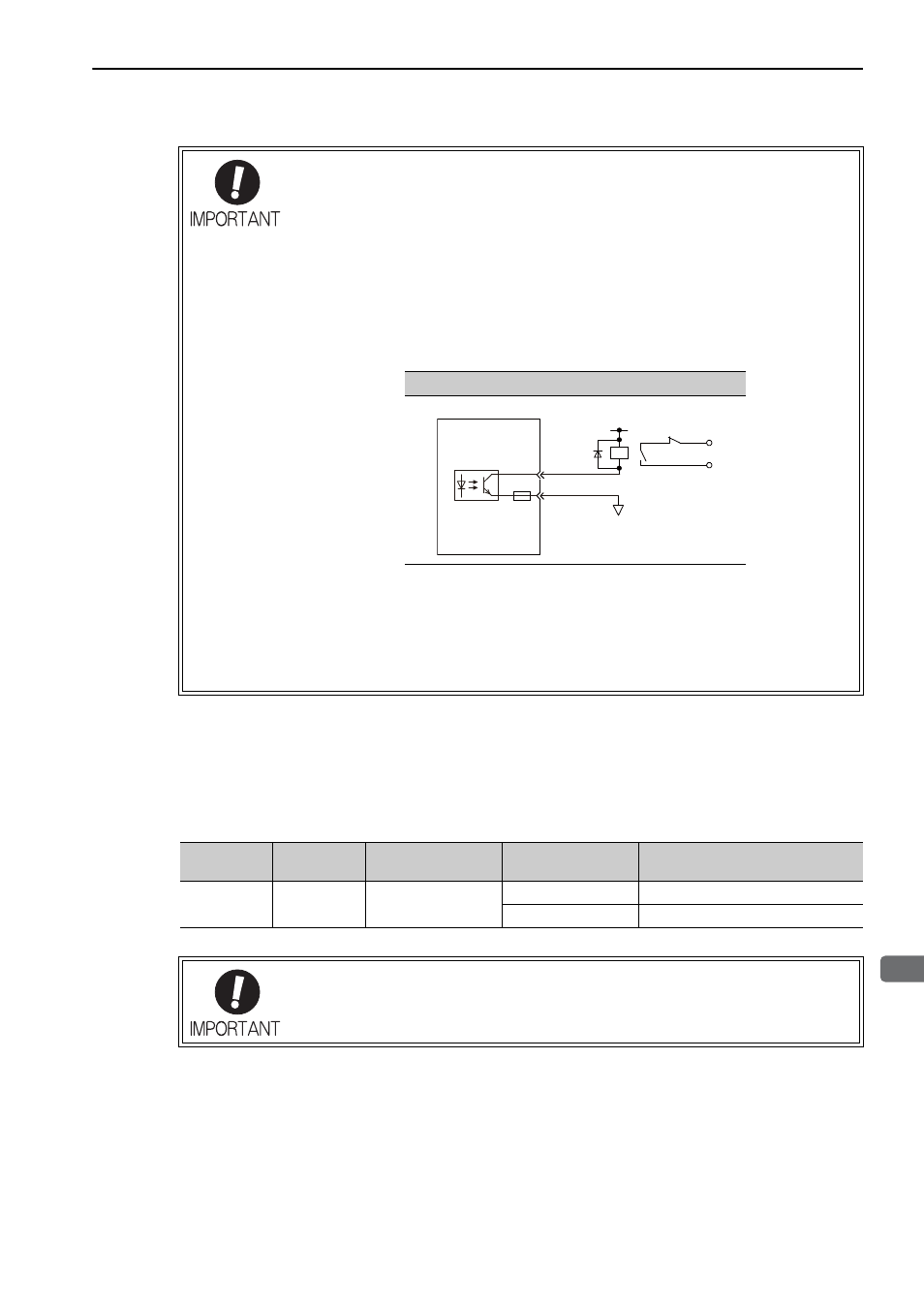
Relay Circuit Example
0 V
Emergency stop
5 to 24 VDC
SERVOPACK
Photocoupler
Type
Name
Connector
Pin Number
Setting
Meaning
Output
/BK
Must be allocated
ON (closed)
Releases the brake.
OFF (open)
Applies the brake.
The /BK signal is still ON during overtravel and the brake is still released.