Test signals – Altera IP Compiler for PCI Express User Manual
Page 144
5–58
Chapter 5: IP Core Interfaces
Test Signals
IP Compiler for PCI Express User Guide
August 2014
Altera Corporation
Test Signals
The test_in and test_out busses provide run-time control and monitoring of the
internal state of the IP cores. Additional signals in IP Compiler for PCI Express
variations with an Avalon-ST interface provide status on the Avalon-ST interface.
describes the test signals for the hard IP implementation.
c
Altera recommends that you use the test_out and test_in signals for debug or
non-critical status monitoring purposes such as LED displays of PCIe link status.
They should not be used for design function purposes. Use of these signals will make
it more difficult to close timing on the design. The signals have not been rigorously
verified and do not function as documented in some corner cases.
The debug signals provided on test_out depend on the setting of test_in[11:8].
provides the encoding for test_in.
phystatus<n>_ext/
pipe_ext_phystatus<n>_ext
I
PHY status <n>. This signal communicates completion of several PHY
requests.
rxelecidle<n>_ext/
pipe_ext_rxelecidle<n>_ext
I
Receive electrical idle <n>. This signal forces the receive output to
electrical idle.
rxstatus<n>_ext[2:0]/
pipe_ext_rxstatus<n>_ext[2:0]
I
Receive status <n>. This signal encodes receive status and error codes
for the receive data stream and receiver detection.
pipe_rstn/
not available
O
Asynchronous reset to external PHY. This signal is tied high and expects
a pull-down resistor on the board. During FPGA configuration, the pull-
down resistor resets the PHY and after that the FPGA drives the PHY out
of reset. This signal is only on IP cores configured for the external PHY.
pipe_txclk/not available
O
Transmit datapath clock to external PHY. This clock is derived from
refclk
and it provides the source synchronous clock for the transmit
data of the PHY.
rate_ext/rate_ext
O
When asserted, indicates the interface is operating at the 5.0 Gbps rate.
This signal is available for simulation purposes only in the hard IP
implementation.
Notes to
:
(1) where <n> is the lane number ranging from 0-7
(2) For variants that use the internal transceiver, these signals are for simulation only. For Quartus II software compilation, these pipe signals can
be left floating.
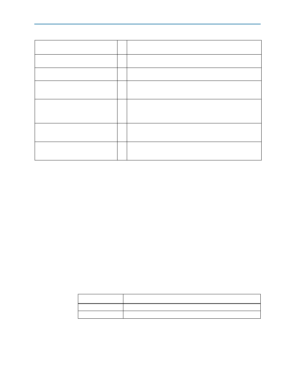
Table 5–31. PIPE Interface Signals (Part 2 of 2)
Signal Name in
Qsys
I/O
Description
Table 5–32. Decoding of test_in[11:8]
test_in[11:8] Value
Signal Group
4’b0011
All other values
Reserved