Pci registers – Altera IP Compiler for PCI Express User Manual
Page 47
Chapter 3: Parameter Settings
3–11
IP Core Parameters
August 2014
Altera Corporation
IP Compiler for PCI Express User Guide
PCI Registers
The ×1 and ×4 IP cores support memory space BARs ranging in size from 128 bits to
the maximum allowed by a 32-bit or 64-bit BAR.
The ×1 and ×4 IP cores in legacy endpoint mode support I/O space BARs sized from
16 Bytes to 4 KBytes. The ×8 IP core only supports I/O space BARs of 4 KBytes.
I
describes the PCI register parameters.
Application clock
62.5 MHz
125 MHz
250 MHz
Specifies the frequency at which the application interface clock operates.
This frequency can only be set to 62.5 MHz or 125 MHz for some Gen1
×1 variations. For all other variations this field displays the frequency of
operation which is controlled by the number of lanes, application
interface width and Max rate setting. Refer to
Table 4–1 on page 4–4
for
a list of the supported combinations.
Max rate
Gen 1 (2.5 Gbps)
Gen 2 (5.0 Gbps)
Specifies the maximum data rate at which the link can operate. The Gen2
rate is only supported in the hard IP implementations. Refer to
for a complete list of Gen1 and Gen2 support in the hard IP
implementation.
Test out width
0, 9, 64, 128 or 512
bits
Indicates the width of the test_out signal. The following widths are
possible:
Hard IP test_out width: None, 9 bits, or 64 bits
Soft IP ×1 or ×4 test_out width: None, 9 bits, or 512 bits
Soft IP ×8 test_out width: None, 9 bits, or 128 bits
Most of these signals are reserved. Refer to
for more information.
Altera recommends the 64-bit width for the hard IP implementation.
HIP reconfig
Enable/Disable
Enables reconfiguration of the hard IP PCI Express read-only
configuration registers. This parameter is only available for the hard IP
implementation.
Notes to
(1) To specify an IP Compiler for PCI Express that targets a Stratix IV GT device, select Stratix IV GX as the PHY type, You must make sure that any
transceiver settings you specify in the transceiver parameter editor are valid for Stratix IV GT devices, otherwise errors will result during
Quartus II compilation.
(2) When you configure the ALT2GXB transceiver for an Arria GX device, the Currently selected device family entry is Stratix II GX. However you
must make sure that any transceiver settings applied in the ALT2GX parameter editor are valid for Arria GX devices, otherwise errors will result
during Quartus II compilation.
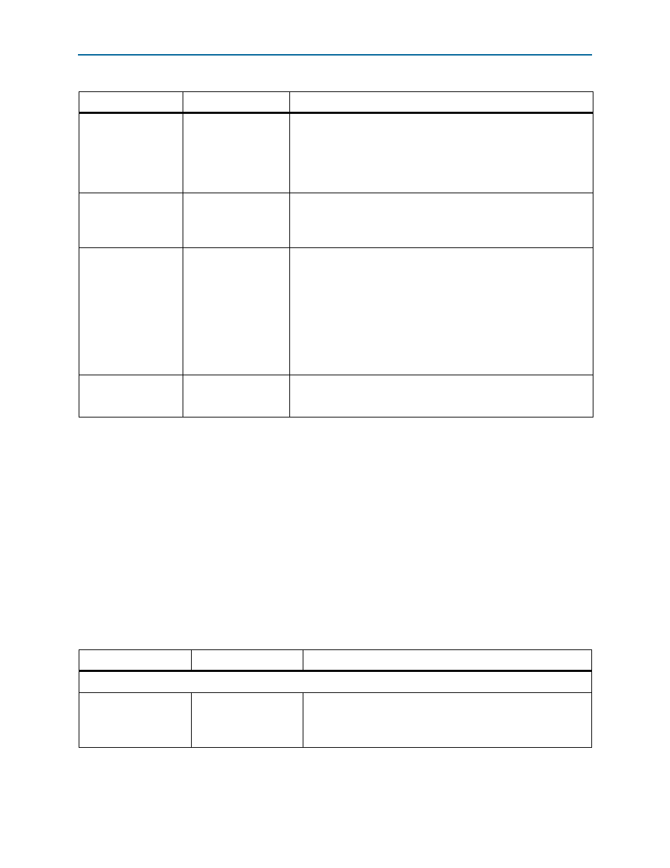
Table 3–9. System Settings Parameters (Part 4 of 4)
Parameter
Value
Description
Table 3–10. PCI Registers (Part 1 of 3)
Parameter
Value
Description
PCI Base Address Registers (0x10, 0x14, 0x18, 0x1C, 0x20, 0x24)
BAR Table (BAR0)
BAR type and size
BAR0 size and type mapping (I/O space
, memory space). BAR0
and BAR1 can be combined to form a 64-bit prefetchable BAR. BAR0
and BAR1 can be configured separate as 32-bit non-prefetchable
memories.)