Chaining dma descriptor tables, Table 15–10 – Altera IP Compiler for PCI Express User Manual
Page 249
Chapter 15: Testbench and Design Example
15–17
Chaining DMA Design Example
August 2014
Altera Corporation
IP Compiler for PCI Express User Guide
Chaining DMA Descriptor Tables
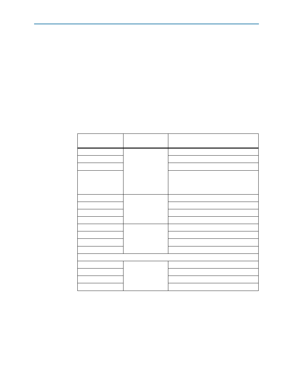
describes the Chaining DMA descriptor table which is stored in the BFM
shared memory. It consists of a four-dword descriptor header and a contiguous list of
<n> four-dword descriptors. The endpoint chaining DMA application accesses the
Chaining DMA descriptor table for two reasons:
■
To iteratively retrieve four-dword descriptors to start a DMA
■
To send update status to the RP, for example to record the number of descriptors
completed to the descriptor header
Each subsequent descriptor consists of a minimum of four dwords of data and
corresponds to one DMA transfer. (A dword equals 32 bits.)
1
Note that the chaining DMA descriptor table should not cross a 4 KByte boundary.
Table 15–10. Chaining DMA Descriptor Table
Byte Address Offset to
Base Source
Descriptor Type
Description
0x0
Descriptor Header
Reserved
0x4
Reserved
0x8
Reserved
0xC
EPLAST - when enabled by the EPLAST_ENA bit
in the control register or descriptor, this location
records the number of the last descriptor
completed by the chaining DMA module.
0x10
Descriptor 0
Control fields, DMA length
0x14
Endpoint address
0x18
RC address upper dword
0x1C
RC address lower dword
0x20
Descriptor 1
Control fields, DMA length
0x24
Endpoint address
0x28
RC address upper dword
0x2C
RC address lower dword
. . .
0x ..0
Descriptor <n>
Control fields, DMA length
0x ..4
Endpoint address
0x ..8
RC address upper dword
0x ..C
RC address lower dword