Altera IP Compiler for PCI Express User Manual
Page 188
9–6
Chapter 9: Optional Features
Instantiating Multiple IP Compiler for PCI Express Instances
IP Compiler for PCI Express User Guide
August 2014
Altera Corporation
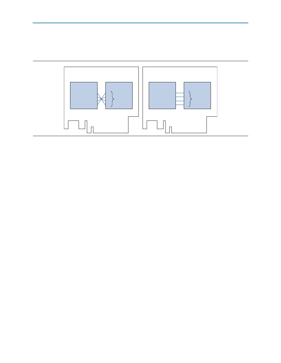
illustrates a PCI Express card with two, ×4 IP cores, a root port and an
endpoint on the top side of the PCB. Connecting the lanes without lane reversal
creates routing problems. Using lane reversal, solves the problem.
Instantiating Multiple IP Compiler for PCI Express Instances
If you want to instantiate multiple IP Compiler for PCI Express instances in your
design, a few additional steps are required. The following sections outline these steps.
Clock and Signal Requirements for Devices with Transceivers
When your design contains multiple IP cores that use the Arria GX or Stratix II GX
transceiver (ALTGX or ALT2GXB) megafunction or the Arria II GX, Cyclone IV GX, or
Stratix IV GX transceiver (ALTGX) megafunction, you must ensure that the
cal_blk_clk
input and gxb_powerdown signals are connected properly.
You must ensure that the cal_blk_clk input to each IP Compiler for PCI Express (or
any other megafunction or user logic that uses the ALTGX or ALT2GXB
megafunction) is driven by the same calibration clock source.
When you use Qsys to create a system with multiple PCI Express IP core variations,
you must filter the signals in the System Contents tab to display the clock
connections. After you display the clock connections, ensure that cal_blk_clk and
any other IP core variations in the system that use transceivers are connected to the
cal_blk_clk
port on the IP Compiler for PCI Express variation.
When you merge multiple IP Compiler for PCI Express instances in a single
transceiver block, the same signal must drive gxb_powerdown to each of the IP
Compiler for PCI Express instances and other IP cores and user logic that use the
ALTGX or ALT2GXB IP cores.
To successfully combine multiple high-speed transceiver channels in the same quad,
they must have the same dynamic reconfiguration setting. To use the dynamic
reconfiguration capability for one transceiver instantiation but not another, in
Arria II GX, Stratix II GX, and Stratix IV GX devices, you must set reconfig_clk to 0
and reconfig_togxb to 3’b010 (in Stratix II GX devices) or 4’b0010 (in Arria II GX or
Stratix IV GX devices) for all transceiver channels that do not use the dynamic
reconfiguration capability.
Figure 9–1. Using Lane Reversal to Solve PCB Routing Problems
0
1
2
3
PCI Express
Root Port
3
2
1
0
PCI Express
Endpoint
0
1
2
3
PCI Express
Root Port
0
1
2
3
PCI Express
Endpoint
No Lane Reversal
Results in PCB Routing Challenge
With Lane Reversal
Signals Route Easily
lane
reversal
no lane
reversal