3 checking output torque limiting during operation – Yaskawa Sigma-5 User Manual: Design and Maintenance - Rotary Motors User Manual
Page 114
4.4 Limiting Torque
4-31
Operation
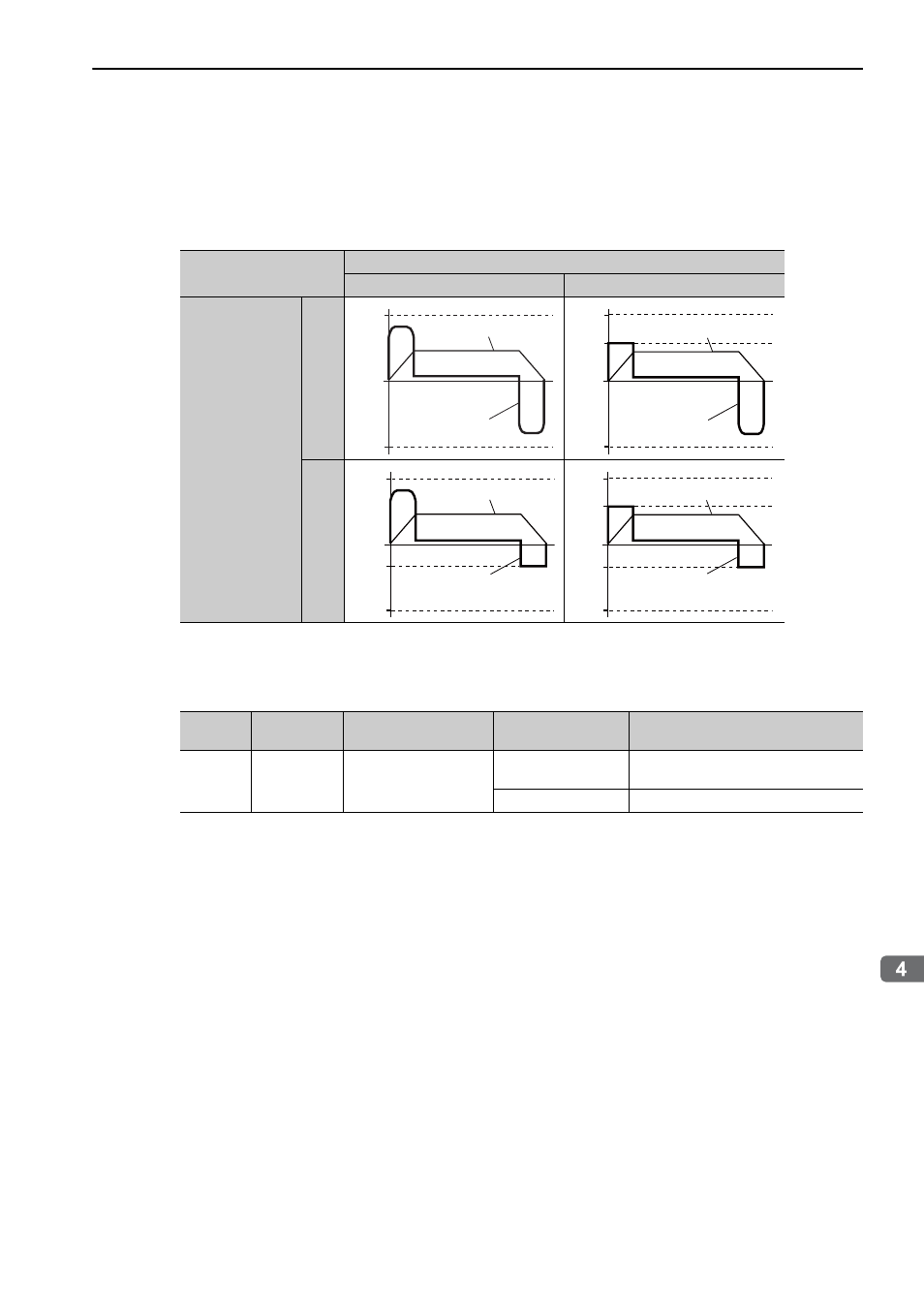
(3) Changes in Output Torque during External Torque Limiting
Changes in output torque when external torque limit is set to 800% are shown with the waveform of Sig-
maWin+.
In this example, the servomotor rotation direction is Pn000.0 = 0 (CCW = forward).
4.4.3 Checking Output Torque Limiting during Operation
The following signal can be output to indicate that the servomotor output torque is being limited.
Note: Use parameter Pn50F.0 to allocate the /CLT signal for use. For details, refer to 3.3.2 Output Signal Allocation.
/P-CL (Forward external torque limit input)
OFF
ON
/N-CL
(Reverse external
torque limit input)
OFF
ON
Pn402
Pn403
0
Torque
Speed
Pn403
0
Pn404
Pn402
Torque
Speed
0
Pn403
Pn405
Pn402
Torque
Speed
0
Pn403
Pn405
Pn404
Pn402
Torque
Speed
Type
Signal Name
Connector
Pin Number
Setting
Meaning
Output
/CLT
Must be allocated
ON (close)
Servomotor output torque is being lim-
ited.
OFF (open)
Torque is not being limited.