7 regenerative resistors connections, 1 connecting regenerative resistors, Warning – Yaskawa Sigma-5 User Manual: Design and Maintenance - Rotary Motors User Manual
Page 76
3 Wiring and Connection
3.7.1 Connecting Regenerative Resistors
3-32
3.7 Regenerative Resistors Connections
If the ability to absorb regenerative energy is insufficient, connect an external regenerative resistor in the
following manner and set the regenerative resistor capacity in Pn600. As for precautions on selecting a regen-
erative resistor and its specifications, refer to
Σ
-V series Product Catalog (KAEP S800000 42).
3.7.1 Connecting Regenerative Resistors
The following instructions show how to connect the regenerative resistors and SERVOPACKs.
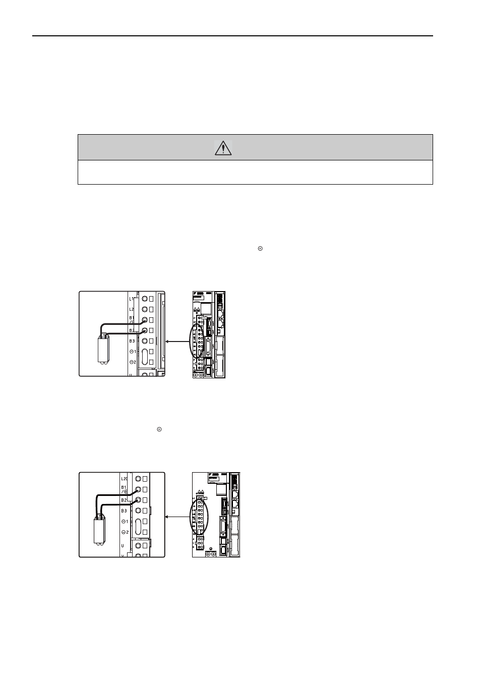
(1) SERVOPACKs: Model SGDV-R70F, R90F, 2R1F, 2R8F, R70A, R90A, 1R6A, 2R8A
Install an external regenerative resistor between the B1/ and B2 terminals. Make the settings for the regener-
ative resistor after it is connected. For information setting the regenerative resistor, refer to 3.7.2 Setting
Regenerative Resistor Capacity.
(2) SERVOPACKs: Model SGDV-3R8A, 5R5A, 7R6A, 120A, 180A, 200A, 330A, 1R9D,
3R5D, 5R4D, 8R4D, 120D, 170D
Disconnect the wiring between the SERVOPACK’s B2 and B3 terminals and connect an external regenerative
resistor between the B1/ and B2 terminals. Make the settings for the regenerative resistor after it is con-
nected. For information setting the regenerative resistor, refer to 3.7.2 Setting Regenerative Resistor Capacity.
Note: Be sure to take out the lead wire between the B2 and B3 terminals.
WARNING
• Be sure to connect the regenerative resistor correctly.
Failure to observe this warning may result in fire or damage to the product.
Enalarged View
Enalarged View