Warning, 3) typical main circuit wiring examples – Yaskawa Sigma-5 User Manual: Design and Maintenance - Rotary Motors User Manual
Page 49
3.1 Main Circuit Wiring
3-5
Wiring and Connection
(3) Typical Main Circuit Wiring Examples
Note the following points when designing the power ON sequence.
• Design the power ON sequence so that main power is turned OFF when a servo alarm signal is output.
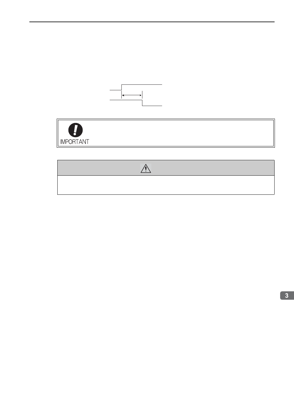
• The ALM signal is output for five seconds max. (1Ry is OFF) when the power is turned ON. Take this into consider-
ation when designing the power ON sequence. Also, use this relay to turn off the main power for the SERVOPACK.
• Select the power supply specifications for the parts in accordance with the input power supply.
The typical main circuit wiring examples are shown below.
• When turning ON the control power supply and the main circuit power supply, turn
them ON at the same time or after the control power supply. When turning OFF the
power supplies, first turn the power for the main circuit OFF and then turn OFF the
control power supply.
WARNING
• Do not touch the power terminals after turning OFF the power. High voltage may still remain in the SER-
VOPACK. When the voltage is discharged, the charge indicator will turn OFF. Make sure the charge indi-
cator is OFF before starting wiring or inspections.
Control power supply
Servo alarm (ALM)
output signal
5.0 s max.