28 (3) safety output circuit – Yaskawa Sigma-5 User Manual: Design and Maintenance - Rotary Motors User Manual
Page 72
3 Wiring and Connection
3.4.2 Sequence Output Circuits
3-28
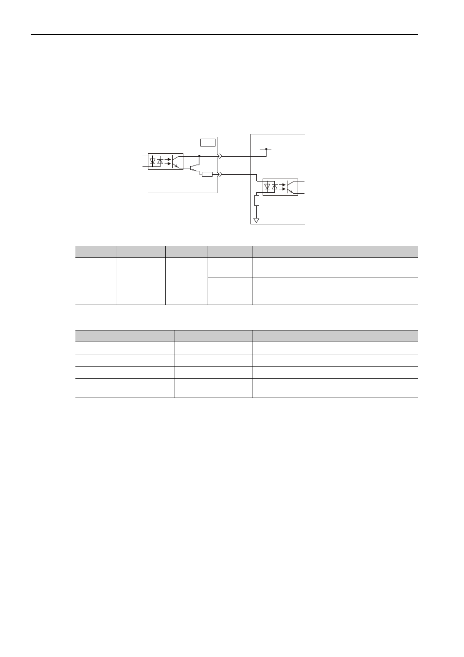
(3) Safety Output Circuit
External device monitor (EDM1), an output signal of safety function, is explained below.
Connection Example
The following figure shows a connection example for the EDM1 output signal.
Specifications
Electrical characteristics of EDM1 signal are as follows.
Host controller
24 V power supply
SERVOPACK
EDM1+
EDM1-
0 V
8
7
CN8
Type
Signal Name
Pin No.
Input Status
Meaning
Output
EDM1
CN8-8
CN8-7
ON
The /HWBB1 signal and /HWBB2 signal are both operat-
ing normally.
OFF
Both the /HWBB1 signal and /HWBB2 signal are not
operating normally or either of the two is not operating
normally.
Items
Characteristic
Remarks
Maximum Allowable Voltage
30 VDC
−
Maximum Current
50 mADC
−
Maximum Voltage Drop at ON
1.0 V
Voltage between EDM1+ to EDM1- at current is 50 mA.
Maximum Delay Time
20 ms
Time from change of /HWBB1, /HWBB2 to change of
EDM1