4 connection to host controller, 1 sequence input circuits, 1) photocoupler input circuit – Yaskawa Sigma-5 User Manual: Design and Maintenance - Rotary Motors User Manual
Page 69
3.4 Connection to Host Controller
3-25
Wiring and Connection
3.4 Connection to Host Controller
This section shows examples of SERVOPACK I/O signal connection to the host controller.
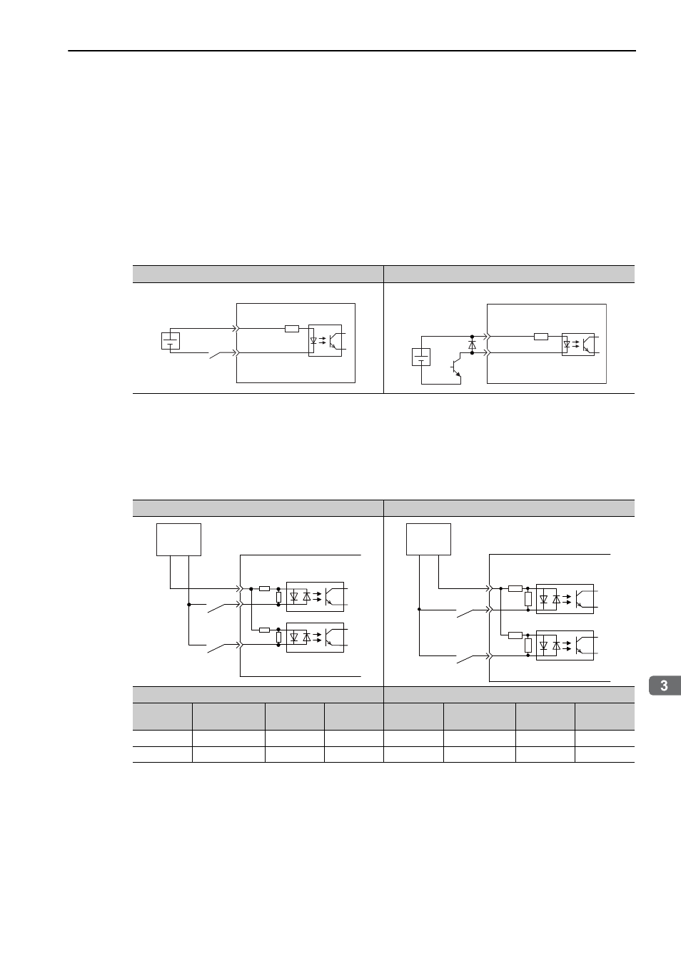
3.4.1 Sequence Input Circuits
(1) Photocoupler Input Circuit
CN1 connector terminals 6 to 13 are explained below.
The sequence input circuit interface connects through a relay or open-collector transistor circuit. Select a low-
current relay if a relay is used. Otherwise, a faulty contact will result.
Note: The 24 VDC external power supply capacity must be 50 mA minimum.
The SERVOPACK’s I/O circuit uses bidirectional photocoupler. Select either the sink circuit or the source cir-
cuit according to the specifications required for each machine.
Note: • The connection example in section 3.2.3 shows the connection using the sink circuit.
• The polarity for turning the input signal ON or OFF differs between the sink circuit and the source circuit.
Relay Circuit Example
Open-collector Circuit Example
Sink Circuit
Source Circuit
Input Signal Polarities
Input Signal Polarities
Signal
Level
Voltage
Level
Contact
Signal
Level
Voltage
Level
Contact
ON
Low (L) level
0 V
Close
ON
High (H) level
24 V
Close
OFF
High (H) level
24 V
Open
OFF
Low (L) level
0 V
Open
SERVOPACK
24 VDC
+24 VIN 3.3 kΩ
/SI3
SERVOPACK
24 VDC
+24 VIN 3.3 kΩ
/SI3
SERVOPACK input
24 V
+
–
SERVOPACK input
24 V
+
–