Yaskawa Sigma-5 User Manual: Design and Maintenance - Rotary Motors User Manual
Page 67
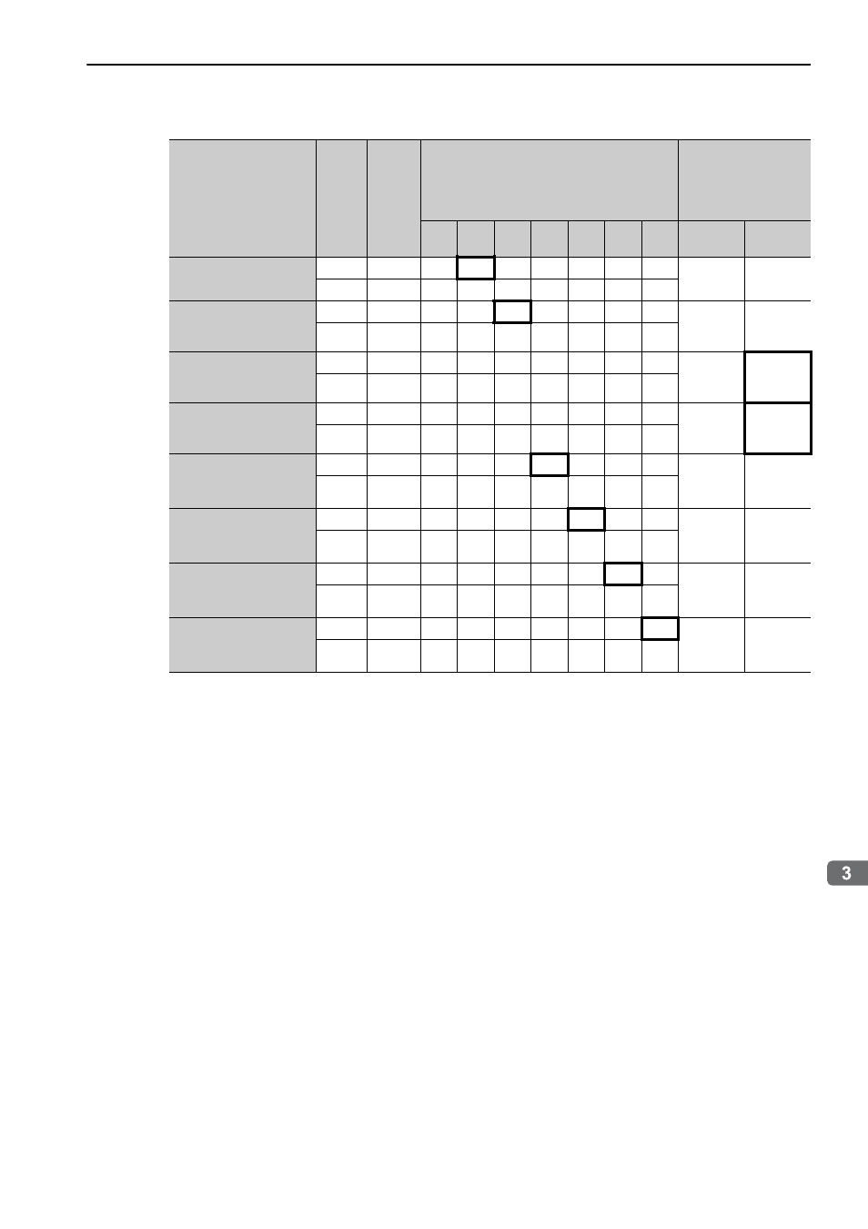
3.3 I/O Signal Allocations
3-23
Wiring and Connection
∗1. For details, refer to the manual of the connected command option module.
∗2. Allocation is not possible.
Input Signal Names
and Parameters
Validity
Level
Input
Signal
CN1 Pin Numbers
Connection Not
Required
(SERVOPACK
judges the
connection)
13
7
8
9
10
11
12
Always
ON
Always
OFF
Forward Run Prohibited
Pn50A.3
H
P-OT
0
1
2
3
4
5
6
7
8
L
/P-OT
9
A
B
C
D
E
F
Reverse Run
Prohibited
Pn50B.0
H
N-OT
0
1
2
3
4
5
6
7
8
L
/N-OT
0
A
B
C
D
E
F
Forward External
Torque Limit
Pn50B.2
L
/P-CL
0
1
2
3
4
5
6
7
8
H
P-CL
9
A
B
C
D
E
F
Reserve External
Torque Limit
Pn50B.3
L
/N-CL
0
1
2
3
4
5
6
7
8
H
N-CL
9
A
B
C
D
E
F
Command Option
Module Input 3
*1
Pn511.0
L
/SI3
0
1
2
3
4
5
6
7
8
H
SI3
9
A
B
C
D
E
F
Command Option
Module Input 4
*1
Pn511.1
L
/SI4
*2
*2
*2
*2
4
5
6
7
8
H
SI4
*2
*2
*2
*2
D
E
F
Command Option
Module Input 5
*1
Pn511.2
L
/SI5
*2
*2
*2
*2
4
5
6
7
8
H
SI5
*2
*2
*2
*2
D
E
F
Command Option
Module Input 6
*1
Pn511.3
L
/SI6
*2
*2
*2
*2
4
5
6
7
8
H
SI6
*2
*2
*2
*2
D
E
F