1 main circuit wiring, 1 main circuit terminals – Yaskawa Sigma-5 User Manual: Design and Maintenance - Rotary Motors User Manual
Page 46
3 Wiring and Connection
3.1.1 Main Circuit Terminals
3-2
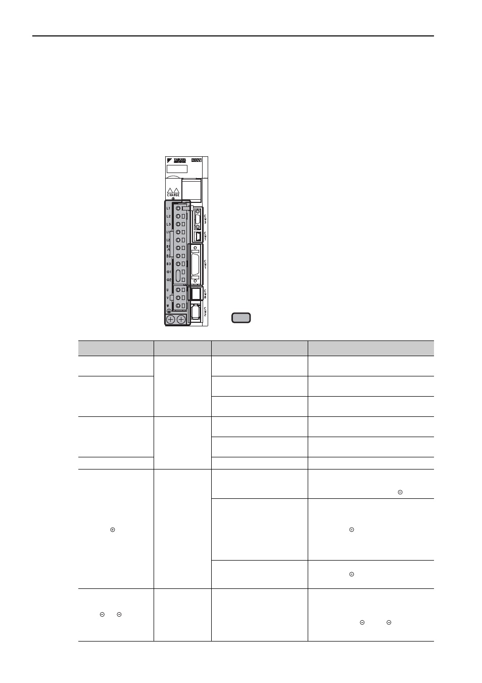
3.1 Main Circuit Wiring
The names and specifications of the main circuit terminals are given on the following page.
This section also describes the general precautions for wiring and precautions under special environments.
3.1.1 Main Circuit Terminals
The names and specifications are shown in the following table.
: Main terminals
SGDV-1R6AE1A
Terminal Symbols
Name
Model SGDV-
Description
L1, L2
Main circuit
input terminals
F
Single-phase 100 to 115 V,
+10% to -15% (50/60 Hz)
L1, L2, L3
A
Three-phase 200 to 230 V,
+10% to -15% (50/60 Hz)
D
Three-phase 380 to 480 V,
+10% to -15% (50/60 Hz)
L1C, L2C
Control power
input terminals
F
Single-phase 100 to 115 V,
+10% to -15% (50/60 Hz)
A
Single-phase 200 to 230 V,
+10% to -15% (50/60 Hz)
24 V, 0 V
D
24 VDC,
±15%
B1/
, B2
*1
External
regenerative
resistor
terminals
R70F, R90F, 2R1F, 2R8F,
R70A, R90A, 1R6A, 2R8A
If the regenerative capacity is insuffi-
cient, connect an external regenerative
resistor (option) between B1/
and B2.
3R8A, 5R5A, 7R6A, 120A,
180A, 200A, 330A, 1R9D,
3R5D, 5R4D, 8R4D, 120D,
170D
Remove the lead or short bar that is short-
circuiting between B2 and B3, and con-
nect an external regenerative resistor
between B1/
and B2 only if the inter-
nal regenerative capacity is insufficient.
Purchase an external regenerative resistor
separately.
470A, 550A, 590A, 780A,
210D, 260D, 280D, 370D
Connect a regenerative resistor unit
between B1/
and B2. Purchase a
regenerative resistor unit separately.
1, 2
*2
DC reactor
connection
terminal for
power supply
harmonic
suppression
A
D
If a countermeasure against power supply
harmonic waves is needed, connect a DC
reactor
between 1
and 2.