Manipulating bitmaps and text, Pixel map fx, 10 manipulating bitmaps and text – ChamSys MagicQ User Manual User Manual
Page 201: 11 pixel map fx
MagicQ User Manual
172 / 355
When the mode is set to chunks single chunks then MagicQ displays each chunk in turn. Each chunk must be separated by a
single underscore (_) character in the text string. Space characters are displayed normally.
22.4.10
Manipulating bitmaps and text
Use the Position attributes of the bitmap layer to make changes to the position of the bitmap / text – set the X or Y position, the
X or Y size and the rotation.
You can play back standard FX on the bitmap layer attributes just like you would on a moving head. For example, to scroll a
bitmap form left to right, first set the X position to centre (X pos is 128) and then add a Ramp Up to the X pos.
Use the Colour attributes to determine the layers of red, green and blue in the bitmap / text. For LED matrix you may find it is
better to use only one colour at a time – for instance, set Red to 255 and Blue and Green to 0.
An iris and a strobe function are also included under the Beam attributes.
It is also possible to use playbacks set as LTP faders in order to control individual parameters of the bitmap from faders.
22.4.11
Pixel Map FX
The FX channels enable FX to be applied to the grid. The FX type selects the FX that is applied. Some of the FX are stand-alone,
e.g. lines and rainbows. Others like move and audio FX are applied on top of the selected bitmap or text.
The FX parameters depend upon the FX type selected – but generally FX parameter 1 is the speed, FX parameter 2 is the offset
between row or column items in the grid, and FX parameter 3 selects the mode – forward, reverse, bounce or twin.
The currently supported FX are:
Vert lines, Horiz lines – enables lines to be moved across the grid. Modify the mode to change thickness of the lines. Change
offset to make patterns rather than lines.
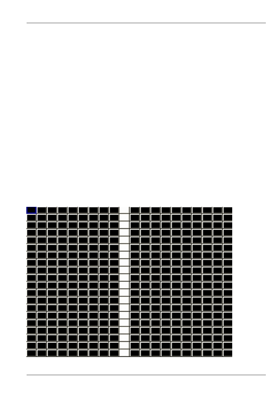
The first image below shows vertical lines with parameter 2 and parameter 3 set to 0. Adjusting parameter 2 gives an offset on
the line as shown in the second image. Adjusting parameter 3 changes the width of the line and changes the mode to bounce
instead of normal in the third image.