IDK MSD-54 Series User Manual
Page 168
MSD-54 SERIES User’s Guide
168
[Step II. Wen setting “PORT” to “Tally”]
PORT:TALLY
DELAY:
0
s000ms
▲▼keys: Set the delay time in seconds (0 to 999).
↓
◄►keys
PORT:TALLY
DELAY: 0s00
0
ms
▲▼keys: Set the delay time in milliseconds (0 to 999).
↓
◄►keys
TALLY22
-
▲▼keys: Select the control of Tally output pin 22 (-, OFF, ON, or
TGL).
↓
◄►keys
TALLY22
ON PULSE:NON
E
▲▼keys: Set the pulse of Tally output pin 22 (NONE, 100 to 9990).
Displayed only if you select “ON” or “OFF” on the previous screen
(setting for control).
↓
◄►keys
TALLY23
-
▲▼keys: Select the control of Tally output pin 23 (-, OFF, ON, TGL).
◄►keys: Moves the cursor to the setting for next pin.
◄►keys
TALLY49
-
▲▼keys: Select the control of Tally output pin 49 (-, OFF, ON, TGL).
◄►keys: Move cursor to the setting for next channel.
↓
◄►keys
MEMO:
1:
▲▼keys Set the “MEMO” (20 to 7D of “9 ASCII codes” except for 2C).
◄►keys: Moves the cursor to the next character (Up to 14 characters).
↓ SET key: Applies settings.
[PRESET COMMAND 1]
NOW UPDATE...
The message is displayed for one second and then previous screen is
displayed automatically.
↓
[COMMAND EDIT]
CMD
1
Note:
If you do not press the “SET” key, the control command is not changed. Make sure to press the “SET” key.
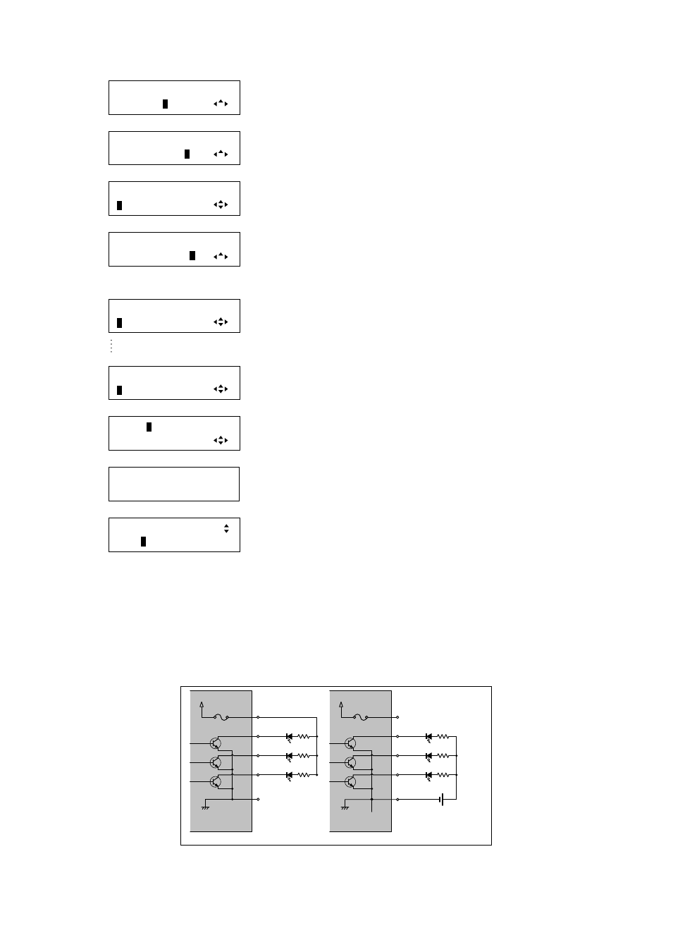
Tally output: only pins 22 to 24 and 47 to 49 can be used for control commands using open collector method.
The maximum supplied currency of internal power (pins1 and 26) is 300 mA. Do not use external power and
internal power at the same time.
The maximum load of pins 22 to 24 and 47 to 49 is DC +48 V and 1 A. (different from the maximum load of
other pins)
Pin 22
Pin 23
Pin 24
Pin 25
+5 V (4.5 V ~ 5.5 V)
Inside of MSD-5404
300 mA
Pins 25 and 50
Pins 1 and 26
Inside of MSD-5404
300 mA
External power
(DC +48V max)
+5 V (4.5 V ~ 5.5 V)
When internal power is used.
When external power is used.
Pin 22
Pin 23
Pin 24
[Figure 8.51] Examples of Tally output circuit