IDK MSD-54 Series User Manual
Page 217
217
■Functions (continuance)
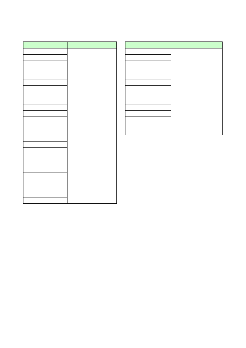
[Table 8.34] Functions of Tally output connector (2/2)
Descriptions
Functions
Descriptions
Functions
V&A:OUT2-IN1
Selecting video and
audio input channels of
OUT 2
*11
V&A:OUT4-IN1
Selecting video and audio
input channels of OUT 4
*11
to
to
V&A:OUT2-IN9
V&A:OUT4-IN9
V&A:OUT2-OFF
V&A:OUT4-OFF
VIDEO:OUT2-IN1
Selecting video input
channels of OUT 2
*11
VIDEO:OUT4-IN1
Selecting video input
channels of OUT 4
*11
to
to
VIDEO:OUT2-IN9
VIDEO:OUT4-IN9
VIDEO:OUT2-OFF
VIDEO:OUT4-OFF
AUDIO:OUT2-IN1
Selecting audio input
channels of OUT 2
*11
AUDIO:OUT4-IN1
Selecting audio input
channels of OUT 4
*11
to
to
AUDIO:OUT2-IN9
AUDIO:OUT4-IN9
AUDIO:OUT2-OFF
AUDIO:OUT4-OFF
V&A:OUT3-IN1
Selecting video and
audio input channels of
OUT 3
*11
PRESET COMMAND
Outputting of control
commands
*12
to
V&A:OUT3-IN9
V&A:OUT3-OFF
VIDEO:OUT3-IN1
Selecting video input
channels of OUT 3
*11
to
VIDEO:OUT3-IN9
VIDEO:OUT3-OFF
AUDIO:OUT3-IN1
Selecting audio input
channels of OUT 3
*11
to
AUDIO:OUT3-IN9
AUDIO:OUT3-OFF
*1
Pins for the currently selected channels are pulled to ground, allowing current to flow through them.
Output target of video and audio depends on channel switching mode. (If video and audio channels are not
the same and ”V&A” is selected for channel switching mode, the video channel is output.)
*2
Pins for the switching mode channels currently selected in parallel are pulled to ground.
*3
Pin is pulled to ground while parallel input is locked.
*4
Control commands that are registered in COMMANDs A to I are pulled to ground. However, each command
execution condition (COMMAND A to I) has two planes (PLANE A and PLANE B). If control commands are
registered in both planes, the control commands are executed alternately every time parallel input of
COMMAND A to I is turned ON/OFF. If PLANE A is set to be executed at the next parallel input ON, it is
pulled to ground (lights); if PLANE B is set to be executed at the next parallel input ON, ground is set
ON/OFF alternately (blinks).
Ground can only be output when the control command is executed according to the setting of “8.12.7
Command key setting”. Ground is set ON/OFF alternately (blinks) when control commands are executed
according to the setting of “8.12.8 Flash time (Command keys and DISPLAY POWER keys)”.
*5
The following pins are pulled to ground:
Pins of “MAX” if maximum level is set; “MIN” if minimum level is set; “MUTE” during mute.
*6
Pulled to ground while a cross point memory is being loaded into settings.
*7
Pulled to ground for 0.5 seconds during preset memory load.