IDK MSD-54 Series User Manual
Page 214
MSD-54 SERIES User’s Guide
214
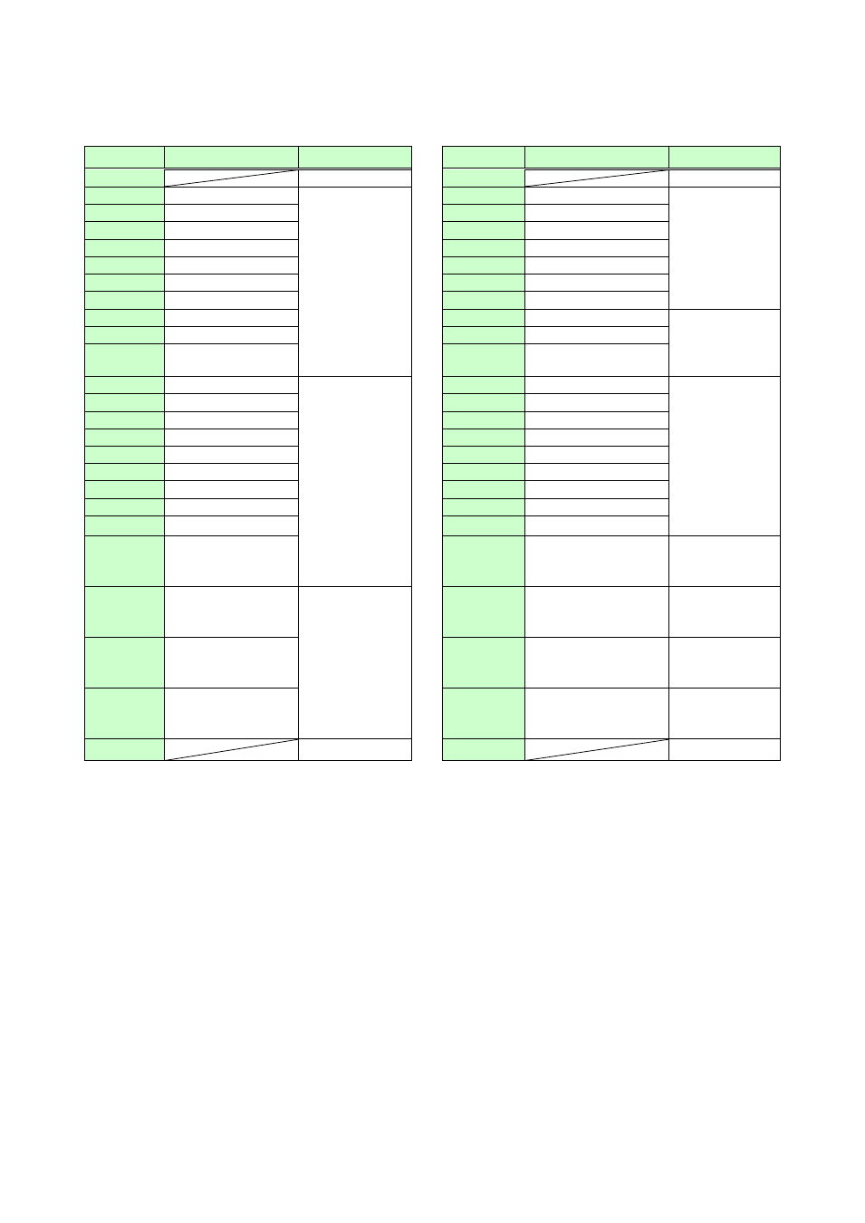
■MSD-5403
[Table 8.31] Factory default of Tally output connectors of MSD-5403
Pin No.
Description
Function
Pin No.
Description
Function
1
+5V
26
+5V
2
OUT1-IN1
Selecting input
channel of OUT
1
*1
27
OUT3-IN4
Selecting input
channel of OUT
3
*1
3
OUT1-IN2
28
OUT3-IN5
4
OUT1-IN3
29
OUT3-IN6
5
OUT1-IN4
30
OUT3-IN7
6
OUT1-IN5
31
OUT3-IN8
7
OUT1-IN6
32
OUT3-IN9
8
OUT1-IN7
33
OUT3-OFF
9
OUT1-IN8
34
SWITCHING–V&A
Selecting
channel
switching mode
*2
10
OUT1-IN9
35
SWITCHING–VIDEO
11
OUT1-OFF
36
SWITCHING–AUDIO
12
OUT2-IN1
Selecting input
channel of OUT
2
*1
37
COMMAND A
Sending control
commands
*3
13
OUT2-IN2
38
COMMAND B
14
OUT2-IN3
39
COMMAND C
15
OUT2-IN4
40
COMMAND D
16
OUT2-IN5
41
COMMAND E
17
OUT2-IN6
42
COMMAND F
18
OUT2-IN7
43
COMMAND G
19
OUT2-IN8
44
COMMAND H
20
OUT2-IN9
45
COMMAND I
21
OUT2-OFF
46
DISPLAY1 POWER
ON
Controlling
display power of
OUT 1
*4
22
OUT3-IN1
Selecting input
channel of OUT
3
*1
47
DISPLAY2 POWER
ON
Controlling
display power of
OUT 2
*4
23
OUT3-IN2
48
DISPLAY3 POWER
ON
Controlling
display power of
OUT 1
*4
24
OUT3-IN3
49
PARALLEL LOCK
Controlling
display power of
OUT 2
*5
25
GND
50
GND
*1
Pins for the currently selected channels are pulled to ground, allowing current to flow through them.
Output target of video and audio depends on channel switching mode. (If video and audio channels are not
the same and ”V&A” is selected for channel switching mode, the video channel is output.)
*2
Pins for the switching mode channels currently selected in parallel are pulled to ground.
*3
Control commands that are registered in COMMANDs A to I are pulled to ground. However, each command
execution condition (COMMAND A to I) has two planes (PLANE A and PLANE B). If control commands are
registered in both planes, the control commands are executed alternately every time parallel input of
COMMAND A to I is turned ON/OFF. If PLANE A is set to be executed at the next parallel input ON, it is
pulled to ground (lights); if PLANE B is set to be executed at the next parallel input ON, ground is set
ON/OFF alternately (blinks).
Ground can only be output when the control command is executed according to the setting of “8.12.7
Command key setting”. Ground is set ON/OFF alternately (blinks) when control commands are executed
according to the setting of “8.12.8 Flash time (Command keys and DISPLAY POWER keys)”.
*4
Pins are pulled to ground when the MSD is turned on.
*5
Pin is pulled to ground while parallel input is locked.