IDK MSD-54 Series User Manual
Page 211
211
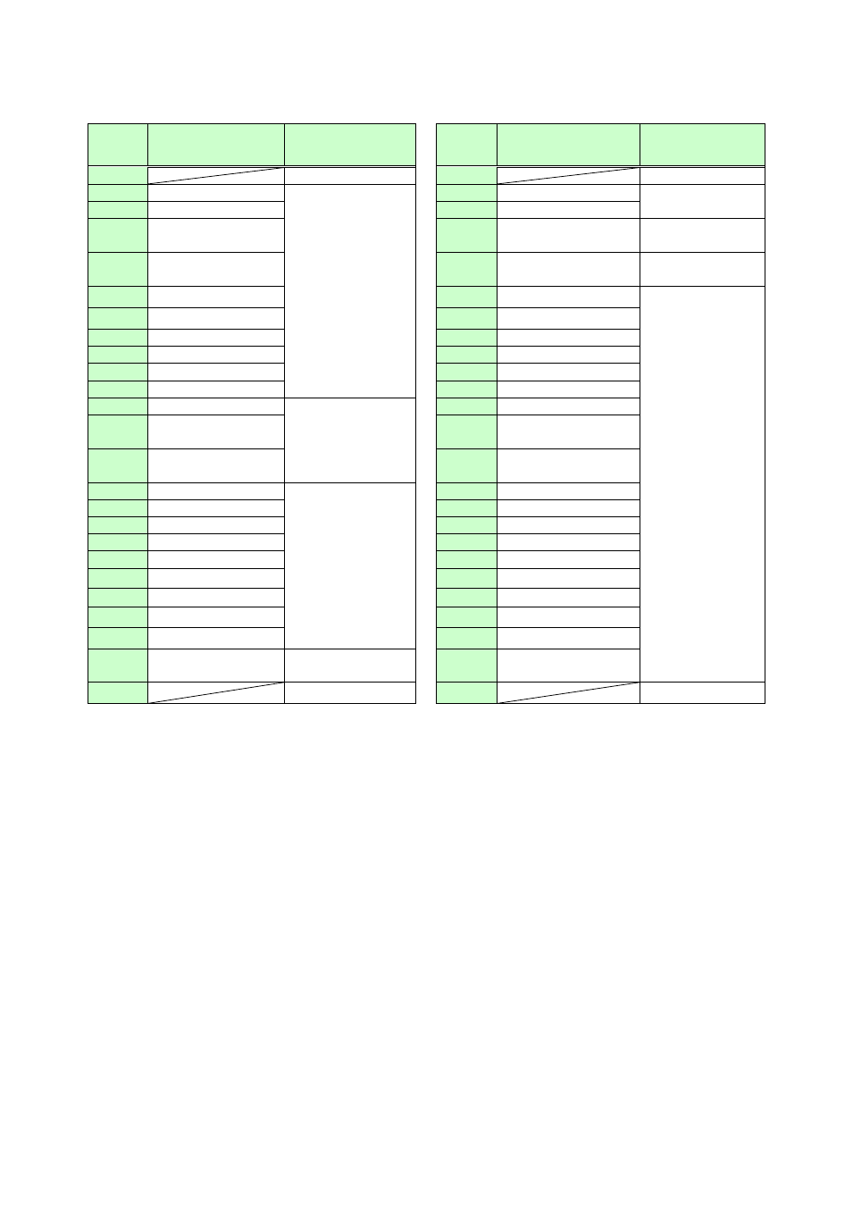
■MSD-5401, MSD-5401SL
[Table 8.29] Factory default of Tally output connectors of MSD-5401, MSD-5401SL
Pin
No.
Description
Function
Pin
No.
Description
Function
1
+5V
26
+5 V
2
OUT1-IN1
Selecting input
channel of OUT1
*1
27
AUDIO–OUT1 MIN
Audio output level
of OUT1
*4
3
OUT1-IN2
28
AUDIO-OUT1 MUTE
4
OUT1-IN3
29
DISPLAY1 POWER
ON
Controlling display
power of OUT1
*5
5
OUT1-IN4
30
PARALLEL LOCK
Lock parallel input
*6
6
OUT1-IN5
31
NOT USE
Not assigned
7
OUT1-IN6
32
NOT USE
8
OUT1-IN7
33
NOT USE
9
OUT1-IN8
34
NOT USE
10
OUT1-IN9
35
NOT USE
11
OUT1-OFF
36
NOT USE
12
SWITCHING–V&A
Selecting channel
switching mode
*2
37
NOT USE
13
SWITCHING–
VIDEO
38
NOT USE
14
SWITCHING–
AUDIO
39
NOT USE
15
COMMAND A
Sending control
commands
*3
40
NOT USE
16
COMMAND B
41
NOT USE
17
COMMAND C
42
NOT USE
18
COMMAND D
43
NOT USE
19
COMMAND E
44
NOT USE
20
COMMAND F
45
NOT USE
21
COMMAND G
46
NOT USE
22
COMMAND H
47
NOT USE
23
COMMAND I
48
NOT USE
24
AUDIO-OUT1 MAX
Audio output level
of OUT1
*4
49
NOT USE
25
GND
50
GND
*1
Pins for the currently selected channels are pulled to ground, allowing current to flow through them.
Output target of video and audio depends on channel switching mode. (If video and audio channels are not
the same and ”V&A” is selected for channel switching mode, the video channel is output.)
*2
Pins for the switching mode channels currently selected in parallel are pulled to ground.
*3
Control commands that are registered in COMMANDs A to I are pulled to ground. However, each command
execution condition (COMMAND A to I) has two planes (PLANE A and PLANE B). If control commands are
registered in both planes, the control commands are executed alternately every time parallel input of
COMMAND A to I is turned ON/OFF. If PLANE A is set to be executed at the next parallel input ON, it is
pulled to ground (lights); if PLANE B is set to be executed at the next parallel input ON, ground is set
ON/OFF alternately (blinks).
Ground can only be output when the control command is executed according to the setting of “8.12.7
Command key setting”. Ground is set ON/OFF alternately (blinks) when control commands are executed
according to the setting of “8.12.8 Flash time (Command keys and DISPLAY POWER keys)
”.
*4
The following pins are pulled to ground:
Pins of “MAX” if maximum level is set; “MIN” if minimum level is set; “MUTE” during mute.
*5
Pins are pulled to ground when the MSD is turned on.
*6
Pin is pulled to ground while parallel input is locked.