14 parallel, Parallel – IDK MSD-54 Series User Manual
Page 192
MSD-54 SERIES User’s Guide
192
8.14 Parallel
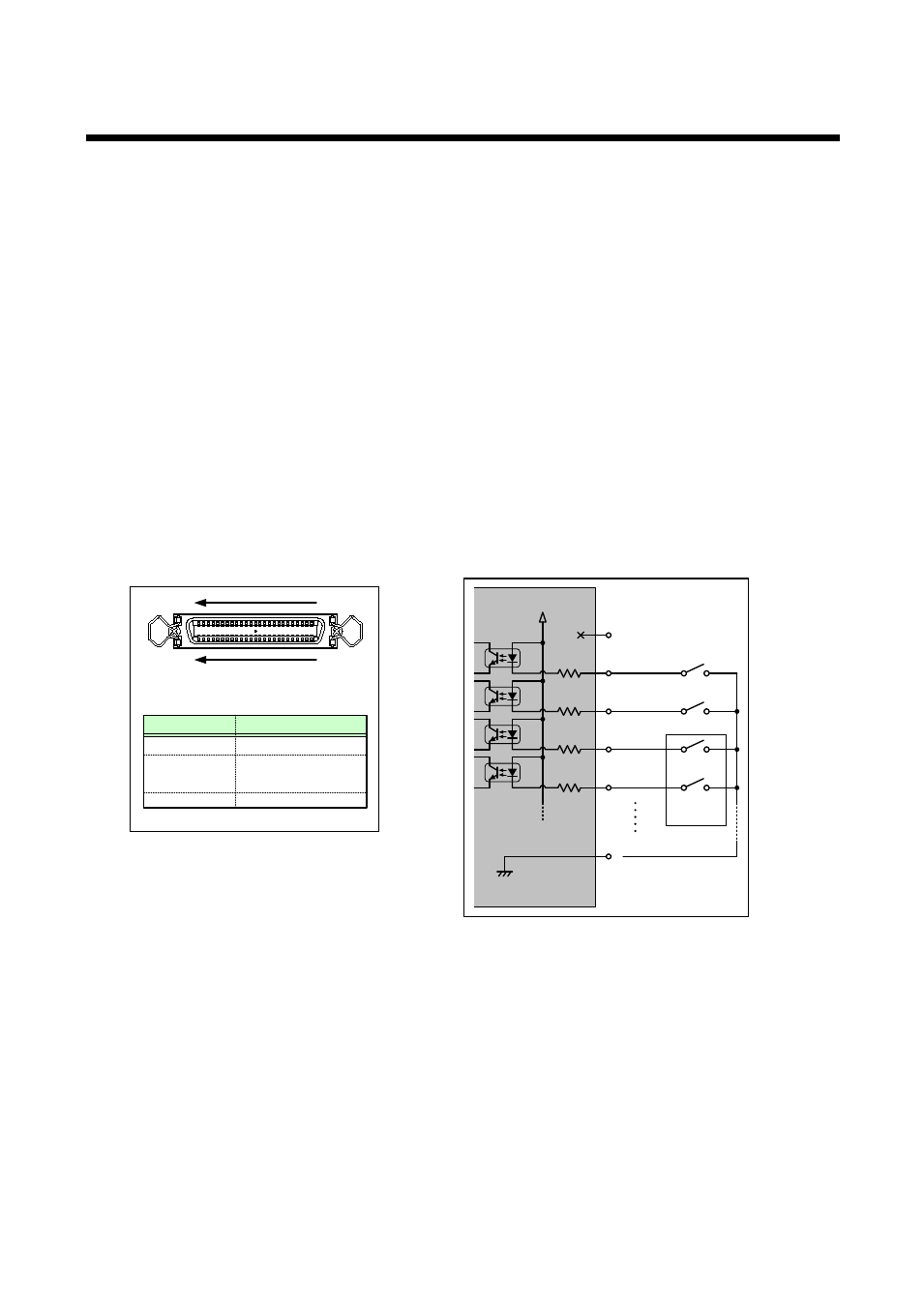
The MSD can be controlled from external contact points. Since photocoupler input is used for parallel input
connectors, it is electrically insulated from the connected device. When each pin of parallel input connector is
pulled to GND, functions assigned to these pins will be performed.
You can assign the following functions to each pin by following the instruction of “8.14.1 Assigning
1. Switching input channels
2. Changing channel switching modes (independent from the front panel switching mode)
3. Sending control commands
4. Locking/releasing parallel inputs
5. Turning on/off display devices
6. Operating menu
7. Locking/releasing front panel
8. Loading cross point/ preset memory
9. Adjusting audio output level
If the contact input operation is unstable due to switch chattering, change the chattering reduction time longer
in “8.14.7 Chattering reduction”.
[Figure 8.60] Example of contact control circuit
[Figure 8.59] Pin locations of parallel
input connector
25, 50
GND
27 ~ 49
Pin
Function
1, 26
2 ~ 24
N.C.(No connection)
Function assignalbe
Amphenol full pitch 50 pin (female)
(MSD-5404 rear)
50
26
25
1
N.C. : No Connection
2nd pin
3rd pin
4th pin
5th pin
25th pin
1st pin
+5V
470
Ω
MSD-5404
Rotary
encoder
Phase A
Phase B