IDK MSD-54 Series User Manual
Page 215
215
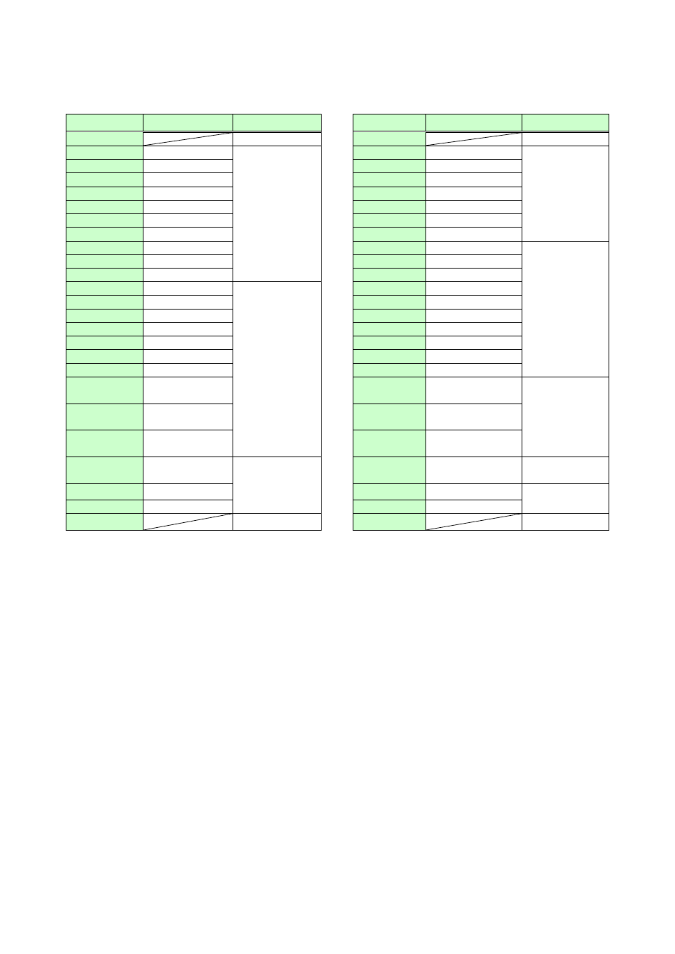
■MSD-5404
[Table 8.32] Factory default of Tally OUTPUT connectors of MSD-5404
Pin No.
Description
Function
Pin No.
Description
Function
1
+5V
26
+5V
2
OUT1-IN1
Selecting input
channel of OUT
1
*1
27
OUT3-IN4
Selecting input
channel of
OUT 3
*1
3
OUT1-IN2
28
OUT3-IN5
4
OUT1-IN3
29
OUT3-IN6
5
OUT1-IN4
30
OUT3-IN7
6
OUT1-IN5
31
OUT3-IN8
7
OUT1-IN6
32
OUT3-IN9
8
OUT1-IN7
33
OUT3-OFF
9
OUT1-IN8
34
OUT4-IN1
Selecting input
channel of
OUT 4
*1
10
OUT1-IN9
35
OUT4-IN2
11
OUT1-OFF
36
OUT4-IN3
12
OUT2-IN1
Selecting input
channel of OUT
2
*1
37
OUT4-IN4
13
OUT2-IN2
38
OUT4-IN5
14
OUT2-IN3
39
OUT4-IN6
15
OUT2-IN4
40
OUT4-IN7
16
OUT2-IN5
41
OUT4-IN8
17
OUT2-IN6
42
OUT4-IN9
18
OUT2-IN7
43
OUT4-OFF
19
OUT2-IN8
44
SWITCHING–
V&A
Selecting
channel
switching mode
*2
20
OUT2-IN9
45
SWITCHING–
VIDEO
21
OUT2-OFF
46
SWITCHING–
AUDIO
22
OUT3-IN1
Selecting input
channel of OUT
3
*1
47
PARALLEL
LOCK
Lock parallel
input
*3
23
OUT3-IN2
48
NOT USE
Not assigned
24
OUT3-IN3
49
NOT USE
25
GND
50
GND
*1
Pins for the currently selected channels are pulled to ground, allowing current to flow through them.
Output target of video and audio depends on channel switching mode. (If video and audio channels are not
the same and ”V&A” is selected for channel switching mode, the video channel is output.)
*2
Pins for the switching mode channels currently selected in parallel are pulled to ground.
*3
Pin is pulled to ground while parallel input is locked.