IDK MSD-54 Series User Manual
Page 176
MSD-54 SERIES User’s Guide
176
Execution condition
1st
2nd
3rd
4th
5th
6th
7th
8th
9th
10th
COMMAND A
COMMAND B
COMMAND C
1
2
3
4
5
30
31
32
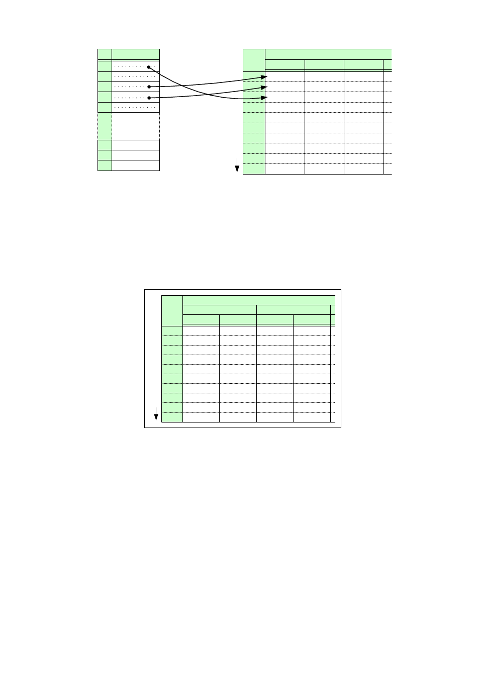
Control commands
Execution order
Associating
commands
COMMAND 1
COMMAND 3
COMMAND 4
COMMAND 1 to 32
[Figure 8.54] Associating control command
For association of control command execution keys (COMMANDs A to I), each execution condition has two
planes. Normally, use only “PLANE A”, but if you want to operate different operations alternately at every time
execution conditions are met, turn “TOGGLE” to “ON” and associate PLANE A and PLANE B separately. You
can select which command will be executed at start-up of the MSD from “AUTO”, “PLANE A”, or “PLANE B”. If
you select “AUTO”, the opposite plane of the plane executed immediately before turning off the MSD will be
executed. “TOGGLE” of all execution conditions is set to “OFF” by default.
[Figure 8.55] Associating control command execution keys
When PLANE B is executed, LEDs for control command execution keys on the front panel and Tally output
are illuminated (PLANE A will be executed at the next press); when PLANE A is executed, the LEDs blink
(PLANE B will be executed at the next press).
PLANE B
PLANE A
PLANE B
PLANE A
Execution condition
1st
2nd
3rd
4th
5th
6th
7th
8th
9th
10th
COMMAND A
COMMAND 3 COMMAND 4
COMMAND B
Execution order