Encoder, Digital filter, Encoder dac digital filter – Yaskawa LEGEND-MC User Manual
Page 36: Current source, Velocity loop
26
LEGEND-MC User’s Manual
For example, a current amplifier with K
a
= 2 A/V with the motor described by the previous example will
have the transfer function:
P/V = 1000/s
2
[rad/V]
Encoder
The encoder generates N pulses per revolution. It outputs two signals, Channel A and B, which are in
quadrature. Due to the quadrature relationship between the encoder channels, the position resolution is
increased to 4N quadrature counts/rev.
The model of the encoder can be represented by a gain of:
K
f
= 4N/2
π [count/rad]
For example, a 1000 lines/rev encoder is modeled as:
K
f
= 638
DAC
The DAC or D-to-A converter converts a 16-bit number to an analog voltage. The input range of the
numbers is 65536 and the output voltage range is +/-10V or 20V. Therefore, the effective gain of the DAC
is:
K= 20/65536 = 305
µVolt/count
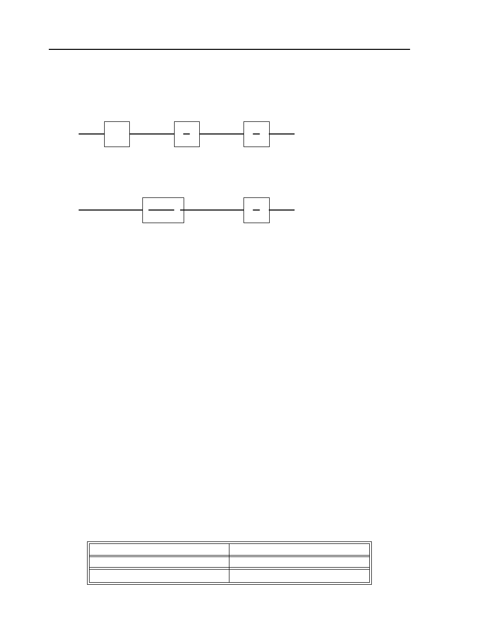
Digital Filter
The digital filter has a transfer function of D(z) = K(z-A)/z + Cz/z-1 and a sampling time of T.
The filter parameters, K, A and C are selected by the instructions KP, KD, KI or by GN, ZR and KI,
respectively. The relationship between the filter coefficients and the instructions are:
K = KP + KD
or K = GN
A = KD/(KP + KD)
or A = ZR
C = KI/8
K
a
K
t
JS
1
S
V
I
W
P
CURRENT SOURCE
1
S
V
W
P
VELOCITY LOOP
1
K
g
(ST
1
+1)