Bode plot of the open loop transfer function, Finally, the phase margin, pm, equals, Next, we discuss the design of control systems – Yaskawa LEGEND-MC User Manual
Page 39
29
LEGEND-MC User’s Manual
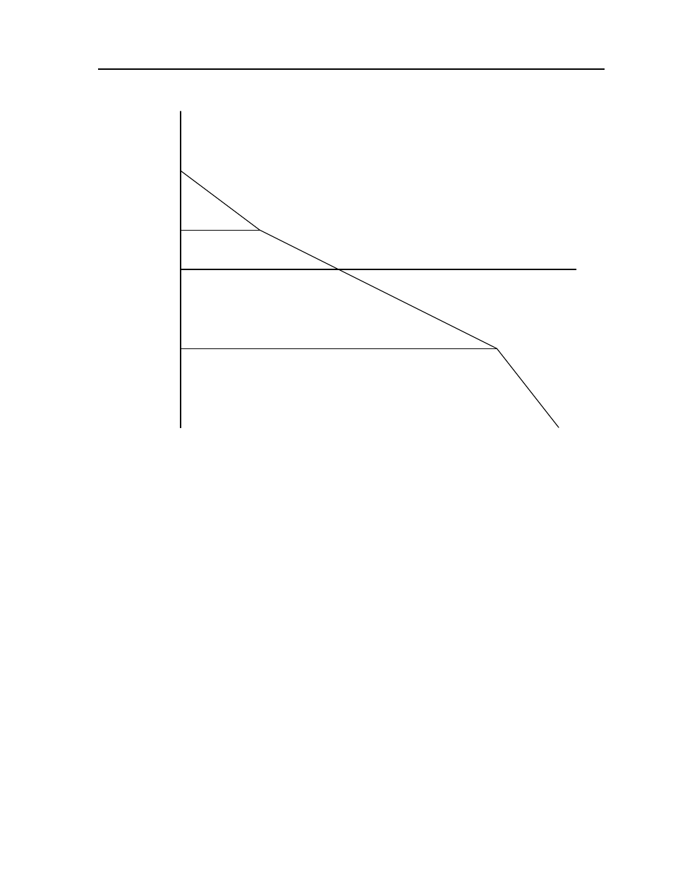
To analyze the system stability, determine the crossover frequency,
ω
c
at which A(j
ω
c
) equals one. This
can be done by the Bode plot of A(j
ω
c
), as shown in the following illustration:
Bode plot of the open loop transfer function
For the given example, the crossover frequency was computed numerically resulting in 200 rad/s.
Next, we determine the phase of A(s) at the crossover frequency:
A(j200) = 390,000 (j200+51)/[(j200)
2
. (j200 + 2000)]
α = Arg[A(j200)] = tan
-1
(200/51)-180
° -tan
-1
(200/2000)
α = 76° - 180° - 6° = -110°
Finally, the phase margin, PM, equals:
PM = 180
° + α = 70°
As long as PM is positive, the system is stable. However, for a well damped system, PM should be
between 30 degrees and 45 degrees. The phase margin of 70 degrees given above indicated overdamped
response.
Next, we discuss the design of control systems.
1
4
0.1
50
200
2000
W (rad/s)
Magnitude