Yaskawa LEGEND-MC User Manual
Page 45
35
LEGEND-MC User’s Manual
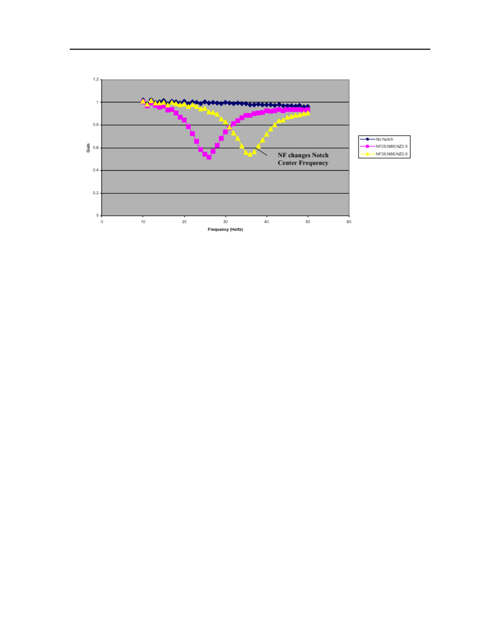
These graphs show how NF, NB, and NZ determine the characteristics of the filter. In particular, NB
specifies the bandwidth that is rejected (Figure 1). A larger NB causes a larger range of frequencies to be
attenuated. The ratio of NB/NZ controls the amount of attenuation, or depth of the notch (Figure 2). A
larger ratio causes a higher amount of attenuation. However, a ratio equal to one should have very little,
or no effect, on the output (Figure 3). A ratio greater than one will amplify the output signal (Figure 3)
causing a resonance. For consistency, these notch waveforms all have a center frequency of 25Hz, except
for the last one (Figure 4) which has a NF of 35 and is therefore shifted to the right.
A simple method for attaining your NF,NB, and NZ parameters is the following:
•Estimate resonance frequency.
•Set NF to resonance frequency in Hz.
•Set NB = 1/2 NF.
•Set NZ between zero and 5.
Although the theory behind a notch filter is beyond the scope of this application note, a general overview
may clarify how the notch works. As shown, the notch filter compensates for a resonance in the system.
One method of illustrating this is by looking at the poles and zeroes of the transfer function plotted on the
s-plane.