System design and compensation, The analytical method, Consider a system with the following parameters – Yaskawa LEGEND-MC User Manual
Page 40: Motor, Encoder, Compensation filter, Then the open loop transfer function, a(s), is
30
LEGEND-MC User’s Manual
System Design and Compensation
The closed-loop control system can be stabilized by a digital filter, which is pre-programmed in the
LEGEND-MC controller. The filter parameters can be selected by the user for the best compensation. The
following discussion presents an analytical design method.
The Analytical Method
The analytical design method is aimed at closing the loop at a crossover frequency,
ω
c
, with a phase
margin PM. The system parameters are assumed known. The design procedure is illustrated by a design
example.
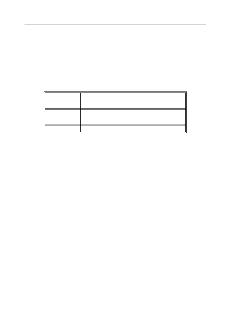
Consider a system with the following parameters:
The DAC of the LEGEND-MC outputs +/-10V for a 14-bit command of +/-8192 counts.
The design objective is to select the filter parameters in order to close a position loop with a crossover
frequency of
ω
c
= 500 rad/s and a phase margin of 45 degrees.
The first step is to develop a mathematical model of the system, as discussed in the previous system.
Motor:
M(s) = P/I = K
t
/Js
2
= 1000/s
2
Amp:
K
a
= 2 [Amp/V]
DAC
K
d
= 10/8192:
Encoder:
K
f
= 4N/2
π = 636
ZOH:
H(s) = 2000/(s+2000)
Compensation Filter:
G(s) = P + sD
The next step is to combine all the system elements, with the exception of G(s), into one function, L(s):
SL(s) = M(s) K
a
K
d
K
f
H(s) = 1.27*10
7
/[s
2
(s+2000)]
Then the open loop transfer function, A(s), is:
A(s) = L(s) G(s)
K
t
Nm/A
Torque constant
J = 2 * 10
-4
kg.m
2
System moment of inertia
R = 2
W
Motor resistance
K
a
= 2
Amp/Volt
Current amplifier gain
N = 1000
Counts/rev
Encoder line density