H3 analog inputs, Programming 96 – Yaskawa F7 Drive Programming Manual User Manual
Page 104
Programming 96
H3 Analog Inputs
H3-01 Terminal A1 Signal Level Selection
The H3-01 parameter (Terminal A1 Signal Level) allows the programmer to specify the signal that will be applied to the A1
analog input. The A1 analog input can accept either a 0 to10 Vdc or -10 to +10 Vdc signal as a reference.
H3-02 Terminal A1 Gain Setting
Setting Range:
0.0 to 1000.0%
Factory Default: 100.0%
H3-03 Terminal A1 Bias Setting
Setting Range:
-100.0% to +100.0%
Factory Default: 0.0%
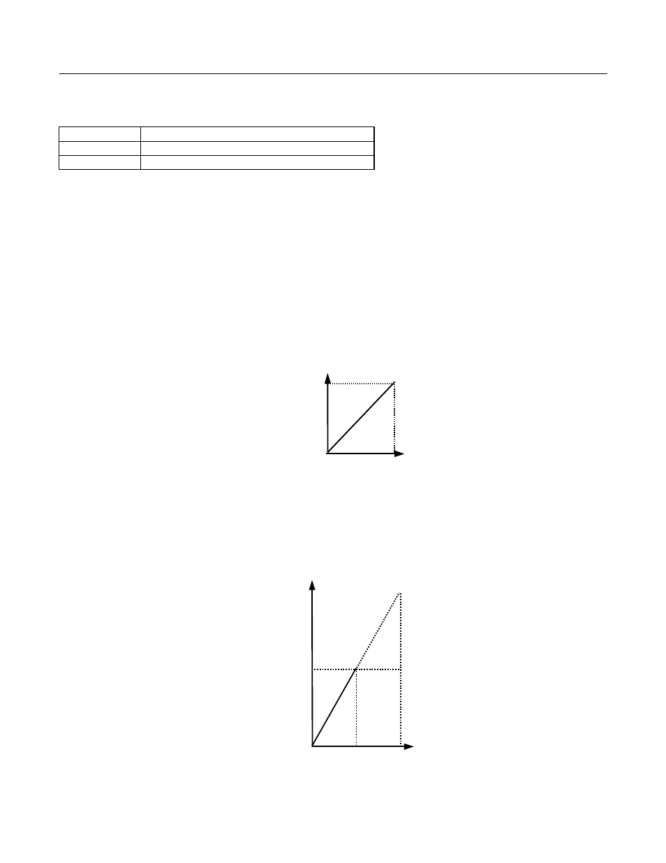
In order to have the Drive properly interpret an analog input, it may be necessary to apply a gain and/or a bias to the signal.
The analog inputs have a resolution of 10 bits (1024 steps). Using the factory default settings for the analog input’s gain and
bias, the 0 to 10Vdc or -10 to +10 Vdc signal at the analog input will yield a 0-100% frequency reference span.
Fig. 63 Output Frequency as Commanded Via Analog Input
If a different span of analog input signal is desirable, it will be necessary to adjust the gain, the bias, or both to allow the analog
input level to generate the desired frequency command. Adjustment of the gain setting will change the frequency reference that is
equivalent to the maximum analog input (10 Vdc). If, for instance, the gain is increased to 200%, then 10Vdc will be equivalent
to a 200% frequency reference and 5 VAC will be equivalent to a 100% frequency reference. Since the Drive output is limited by
the maximum frequency parameter (E1-04), 0-5Vdc will now be equivalent to 0-100% frequency reference span.
Fig. 64 Output Frequency as Commanded via Analog Input with Increased Gain Setting
Setting
Description
0
0 to 10 Vdc
1
-10 to +10 Vdc (factory default)
20mA
4mA
0V
10V
Gain = 100%
Bias = 0%
Ou
tp
ut
F
req
uen
cy
4mA
20mA
0V
10V
Bias = 0%
Out
put
F
requ
enc
y
Gain =200%
100%
5V
12mA