Programming 179, Serial communications setup, Pulse i/o setup – Yaskawa F7 Drive Programming Manual User Manual
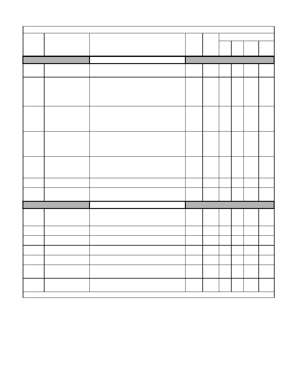
Page 187: Table a.1 f7 parameter list (continued)
Programming 179
Serial Communications Setup
H5-01
Drive Node Address
Serial Comm Adr
Selects Drive station node number (address) for Modbus terminals
R+, R-, S+, S-. The Drive’s power must be cycled for the setting to
take effect.
0 to 20
Hex
1F
A
A
A
A
H5-02
Communication Speed
Selection
Serial Baud Rate
Selects the baud rate for Modbus terminals R+, R-, S+ and S-. The
Drive’s power must be cycled for the setting to take effect.
0: 1200 bps
1: 2400 bps
2: 4800 bps
3: 9600 bps
4: 19200 bps
0 to 4
3
A
A
A
A
H5-03
Communication Parity
Selection
Serial Com Sel
Selects the communication parity for Modbus terminals R+, R-, S+
and S-. The Drive’s power must be cycled for the setting to take
effect.
0: No Parity
1: Even Parity
2: Odd Parity
0 to 2
0
A
A
A
A
H5-04
Stopping Method After
Communication Error
Serial Fault Sel
Selects the stopping method when a communication timeout fault
(CE) is detected.
0: Ramp to Stop
1: Coast to Stop
2: Fast-Stop
3: Alarm Only
0 to 3
3
A
A
A
A
H5-05
Communication Fault
Detection Selection
Serial Flt Dtct
Enables or disables the communications timeout fault (CE).
0: Disabled - A communication loss will not cause a
communication fault.
1: Enabled - If communication is lost for more than 2 seconds, a
CE fault will occur.
0 to 1
1
A
A
A
A
H5-06
Drive Transmit Wait Time
Transmit WaitTIM
Set the delay time from when the Drive receives data to when the
Drive sends data.
5 to 65
5ms
A
A
A
A
H5-07
RTS Control Selection
RTS Control Sel
Enables or disables “request to send” (RTS) control:
0: Disabled - RTS is always on
1: Enabled - RTS turns on only when sending
0 to 1
1
A
A
A
A
Pulse I/O Setup
H6-01
Terminal RP Pulse Train
Input Function Selection
Pulse Input Sel
Selects the function of pulse train terminal RP.
0: Frequency reference
1: PID feedback value
2: PID setpoint value
0 to 2
0
A
A
A
A
H6-02
Pulse Train Input Scaling
Pulse In Scaling
Sets the number of pulses (in Hz) that is equal to the maximum
output frequency E1-04.
1000 to
32000
1440Hz
A
A
A
A
H6-03
Pulse Train Input Gain
Pulse Input Gain
Sets the output level when the pulse train input is at 100% as a
percentage of maximum output frequency E1-04.
0.0 to
1000.0
100.0%
A
A
A
A
H6-04
Pulse Train Input Bias
Pulse Input Bias
Sets the output level when the pulse train input is 0Hz as a
percentage of maximum output frequency E1-04.
-100.0 to
100.0
0.0%
A
A
A
A
H6-05
Pulse Train Input Filter Time
Pulse In Filter
Sets the pulse train input filter time constant in seconds.
0.00 to
2.00
0.10sec
A
A
A
A
H6-06
Terminal MP Pulse Train
Monitor Selection
Pulse Moni Sel
Select the pulse train monitor output terminal MP function (value
of the
part of U1-
). See Table A2 for the list of U1
monitors.
1, 2, 5,
20, 24,
31, 36
2
A
A
A
A
H6-07
Pulse Train Monitor Scaling
Pulse Moni Scale
Sets the number of output pulses when the monitor is 100% (in
Hz). Set H6-06 to 2, and H6-07 to 0, to make the pulse train
monitor output synchronous to the output frequency.
0 to
32000
1440Hz
A
A
A
A
Denotes that parameter can be changed when the Drive is running.
Table A.1 F7 Parameter List (Continued)
Parameter
No.
Parameter Name
Digital Operator Display
Description
Setting
Range
Factory
Setting
Control Method
V/F
V/F
w/
PG
Open
Loop
Vector
Flux
Vector